

|
4QD-TEC
|
|
Arguably, one of the most useful, simple, circuit configurations is this connection of two transistors into a four layer device equivalent to a Unijunction transistor. It is also possibly one of the least valued and least understood of simple circuits. In fact when I started looking out circuits for this page I surprised myself by just how much I had to say about such a simple, two transistor circuit! Yet perhaps I should not be surprised for GE wrote an entire book on the applications of Unijunction transistors and, in performance, this configuration has a lot in common with the UJT. The basic connection of the 4 layer device is shown in the diagram below and the configuration is the basis of Thyristors (or SCRs - Silicon Controlled Rectifiers), Triacs, diacs, SBSs (Silicon Bilateral Switches) as well as the Programmable Unijunction or PUT.
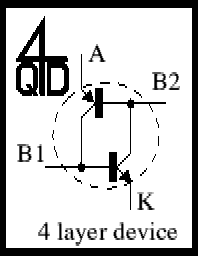
When neither transistor conducts, then no current flows. However as soon as any current flows in either transistor, this current becomes base current for the other and both transistors turn each other hard on. This means that you must use good, low leakage transistors to make this circuit or the leakage current will cause it not to work. However virtually any modern silicon transistor will suffice as manufacturers nowadays generally don't make leaky transistors!
If you cannot see how this is 4 layers consider the two transistors: the top is a P-N-P and the bottom is N-P-N. The base of the top one (N) connects to the collector of the bottom one (also N). Similarly the P of the top collector connects to the P of the bottom's base so the whole becomes an N-P-N-P 4 layer device. It has 4 terminals as shown, but in most practical devices only three are terminated - though which three depends on the device!
As an SCR the terminals are A, K with B1 as the gate. It is quite easy to see how a small base current into B1 causes the device to turn hard on.
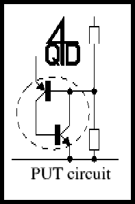
The next picture shows the 4 layer device connected as a PUT: in this two resistors define the interbase resistance and the standoff ratio of the normal unijunction. Now I suppose a lot of visitors won't know anything about unijunctions - but I don't intend to cover them here (I could change my mind if I get enough emails!) as they really aren't much use except for oscillators, which I am covering. Anyway, I have always used the transistor pair!
One device which seems to be rather out of favour nowadays is the SBS. It is a trigger device used to fire a Triac. Triacs tend to need a fairly high current pulse to turn them on and this is usually arranged by charging a capacitor and then, when it gets to a set voltage, dumping its charge into the triac gate. The SBS is the device used to do the dump.
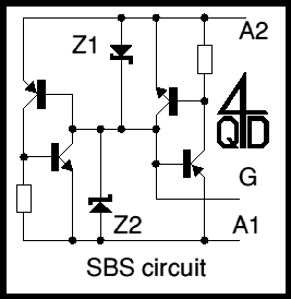
Two identical circuits are arranged in anti-parallel as shown, so that one works for positive voltages, the other for negative. Consider a rising positive voltage, as on a charging capacitor, on A2. The left hand part of the circuit will operate, but at low voltages, since the circuit started at zero, there is no base current so neither transistor conducts. Z1 is forward biased, but with no current flowing, so the full voltage is across Z2. This circuit remains non conducting until Z2 starts to conduct at its breakdown voltage. Now current flows into the base of the left hand PNP and the transistor pair conducts.
You can see that the other half does the same thing for opposite voltage cycle.
In this circuit the base of the transistor is held at 5v (with a 10v supply) by the two 1K resistors. Equal values give a 'stand-off ratio' of 0.5. Obviously this UJT is programmable so this ratio can be changed at will, say between 1K:10K and 10K:1K. If you want to experiment, use a 1K of 2K preset.
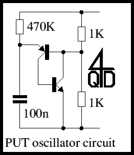
At power up the capacitor will, initially, be discharged, so there is no voltage on the emitter of the PNP transistor - its base-emitter is therefore reverse biased and no current flows. The capacitor starts to charge up towards 10v via the 470K resistor. When it reaches about 5.5 volts the emitter-base junction is no longer reverse biased and a small current starts to flow. Both transistors then turn hard on. The capacitor is quickly discharged through the two transistors. However when the capacitor discharges too far there is no longer enough current available to keep the two transistors conducting - so they turn off. The cycle repeats. The circuit is an oscillator. The current out of the NPN's emitter is pulsed and some circuits put a resistor here to use the pulses. The voltage on the PNP's emitter (which, in a Unijunction, is the emitter) is a good sawtooth, but at a high impedance, so don't load it much. The junction of the two 1K resistors can be used as an output at lower resistance, but (with the values shown) this is a negative-going pulse of about 40 µS at intervals of about 40mS, so about 1:1000 duty cycle!
The two 1K resistors can be changed considerably to vary the sawtooth height (and the frequency). The capacitor can be varied widely to change frequency. You need to keep with a fairly high value where the 470K resistor is or the circuit will not oscillate. The minimum value depends on the gains of the transistors and is lower with low gain transistors, which are not so common nowadays.
This is a good, reliable sawtooth generator and is probably the main use for unijunctions. However there is a variant on this oscillator which I prefer...
To a purist, the '4 layer connection' is not present in this circuit but if you compare it with the circuit above you will see how similar it is. The main advantage is that the pulse output is available from the NPN's collector. I have used a variant on this circuit to flash our Christmas Tree lights - perhaps I'll write that one up for next year!
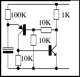
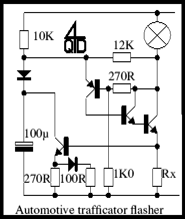
Very similar to the last circuit, the NPN transistor has become a Darlington pair so that it has enough current drive to work the lights. Naturally the second transistor must be a power type large enough to handle the bulb current. Note Rx in the emitter. When the lights are working properly this should drop about 0.75 volts so that it turns on the extra transistor. This transistor discharges the timing capacitor. Because of this slower discharging, the light stays on longer. The cunning thing here is that, if a bulb gets shorted out the capacitor gets discharged very quickly (the diode and 100R see to that) so the effect is clearly visible on the dashboard indicator. Also if a bulb fails open-circuit, the flash rate slows down. Again, clearly visible.
So the pair we are considering here is a Programmable Unijunction - and UJTs are no good for anything except oscillators? Wrong! Here's a bistable using two of the pairs.
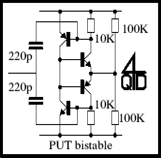
The operation of this circuit is quite obvious - if you understand the basic pair. But this particular circuit also has an interesting application as a 'snap-action' complimentary follower. Remove the two capacitors and drive the circuit via the joined bases. It could have a use as a very fast MOSFET drive circuit.
Schmidt Trigger
This is a Schmidt unlike any you have seen before. It has some unusual properties - some of which are distinct advantages, some are disadvantages. There is no 'best circuit' - different ways of doing a particular function have different uses.
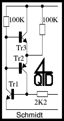
Input is via the 2K2 to the base of Tr1. Initially consider the input at 0v: Tr1 and Tr2 will be off and Tr3 will pull the output high. Now consider the input rising, slowly. As it gets to about 550mV Tr1 will start to conduct. But as soon as any current flows in Tr1 it will turn on Tr2 as well and the pair will snap into conduction. Tr3 will be turned off. In this state the only current flowing into Tr2's emitter is the 100µA (assuming 10v supply) flowing in the 100K connected to the emitter of Tr2. Now current into Tr2's emitter must flow out of its collector and it is this current that keeps Tr1/Tr2 conducting.
Now consider the situation as the input voltage starts to fall. There is 100µA holding the pair on, so to turn them off we must rob this 100µA from Tr1's base. We can only do this by reducing the input by 220mV (100µA through 2K2). So the on point is set by the Vbe and the off point is set by the 2K2.
The main disadvantages are two - firstly the Vbe temperature sensitivity, but a lot of Schmidt trigger circuits do this. Secondly, when I said the current through Tr2 was 100µA I was not considering and load current. This will confuse the situation! The circuit is however very good at switching low with a capacitative load since current supplied by the capacitor tends to aid the collapse of the PUT pair.
Thermostat
OK - so I admit is. This circuit is the same as the last one! Here is a practical use for the Schmidt trigger.
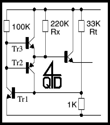
Well I hope you can see the similarity! Yet there is no input.... The 2K2 has become 1K and the 33K biases the base of Tr1 to 440mV (with a 15v supply). The 33K sets the operating point and the circuit does require a stable voltage, if only to drive this bias chain.
Now consider the situation as Tr1 heats up. As a semiconductor warms the voltage across it reduces: around room temperature the reduction is about 2mV per degree Celsius. If the Vbe drops by about 110mV, the 440mV will just start it conducting. 110mV should correspond to 55°C - so we would expect this to operate at around 80°C. Simply adjust the 33K to get the correct operating temperature.
As explained above, the 220K in conjunction with the supply voltage defines a current which must be removed by the 1K to turn off the thermostat: we are considering 15v supply, so the voltage across the 1K will be 15/(220+1)*1 or 70millivolts corresponding to a temperature drop of about 35°C.
Note the emitter follower at the output to remove the aforementioned affect of the load current.
I have several times used this thermostat and it is a very successful circuit.
Electric Field and Leakage Detector
And now for something totally different. It detects very small currents such as those caused by leakage and changing electric fields.
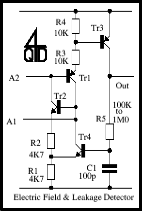
Tr1 and Tr2 are the PUT connected pair. There is nothing to turn them on: Tr1's base has no connection and Tr2's base is only connected to Tr4's collector which cannot supply any current. If Tr4 turned on it would tend to turn off the PUT pair.
If the pair turn on, they pass current into Tr3. Tr3 charges up C1 before it turns on Tr4. Tr4 turns off the PUT pair. So if the pair turn on, they remain on for a short time, then turn of again.
Now here's the fun bit. The PUT pair (connected with no base-emitter resistor to desensitise it) is incredibly sensitive. So sensitive that even a few electrons may be enough to trigger it. So if any charged item moves near one of the bases the very small induced charge is enough to turn it on. Each time it turns on, the output gives a small pulse. Connect a small earpiece to the output and you get something which simulates a Geiger-counter but reacts to charge movement or changing electric field or leakage. All you do is attach a few inches of wire to A1 and A2 to act as aerials.
I've used this as a mains wiring detector: the 'Geiger' screams when near mains wiring. Or it is good as a leakage detector: touch the two aerials onto a piece of glass and breathe on the glass.
The construction of the circuit is very critical: since it detects leakage, any leakage of a circuit board around the bases will cause problems. Either have these terminals in free air or connect them to ptfe stand-offs so they don't touch the circuit board. If the circuit will detect your breath on a glass plate a circuit board would be lethal.
The circuit's other guise is as a person detector. For this the on time needs to be about a second and it triggers an audio oscillator. I've made this up as a box which sits on a table, Can you get near the box without it reacting? Almost everyone carries some sort of charge but it varies a lot with humidity and the clothing the person is wearing so the box likes some people and hardly react to others. I have now added this circuit to this site.
Game referee circuit
Here's another fun circuit. This one is a referee for 'snap' or 'musical chairs' types of game. In 'snap' mode the first player to press their button locks out everyone else whilst in 'musical chairs' mode the last player to press their button stays lit.
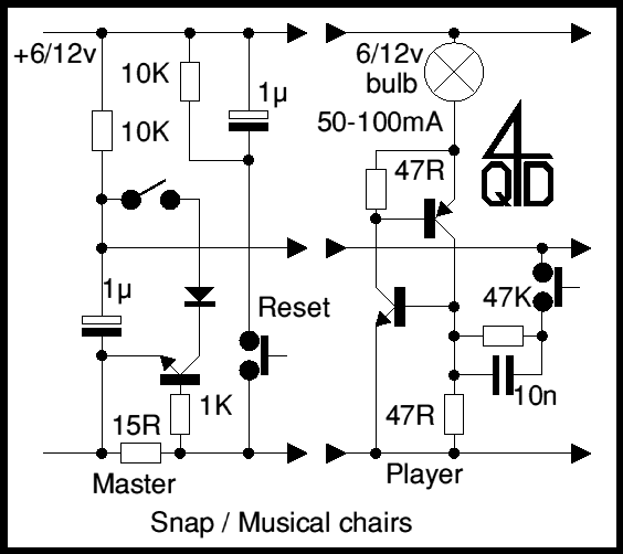
In the master, the 1µ capacitor changes up through the 10K resistor. When a player pushes a button a small charge flows through the player's 10n capacitor and turns on their PUT pair, so the player's bulb lights.
In 'musical chair' mode, the master's mode switch is open (as shown). If a second player presses their switch the current flowing in their bulb causes a positive spike on the negative supply line. This spike is caused because a standard bulb's filament resistance increases as it gets hot: a cold filament will (instantaneously) draw about 10 times the rated operating current. This causes enough drop across the master's 15R resistor to turn off the first player. Thus the bulb of the last player to hit their button stays on.
In 'snap' mode, the master's mode switch must be closed. The current from an illuminated bulb is now sensed by the 15R resistor and causes the transistor to turn on, now discharging the 1µ capacitor diode, so there is no voltage on the centre line and no other player's light can operate.
The PUT complementary pair is actually a very versatile circuit. It is used in the Impulse Changeover Switch elsewhere and I have lots more circuits that use variations on it so you can expect this page to grow!
| 4QD Sites: |