
|
4QD-TEC
|
|
So what on earth is an 'impulse changeover switch'? Easy - a switch which changes state each time it gets an impulse. You may think it's just a fancy name for a bistable - OK I admit it. However in the welding industry we used to use an 'impulse changeover relay' to control the direction of a d.c. motor used to oscillate a welding head between mechanical end stops. There was a roller-lever operated microswitch and two adjustable position blocks. Each time the microswitch hit a block, the relay changed over. How crude can you get?
The problem was - these relays pegged out after so many thousand operations and started to get unreliable so the switch hit a reversing block - and didn't. CRASH. I was asked to design an electronic replacement.
What a cushy job I hear you mutter. But these welding machines used a high frequency, high voltage on the head to start the weld. Take a 110v ac, apply it to a spark gap and a capacitor and a high ratio step-up transformer. Feed to resulting high-frequency, pulsed a.c. to the weld head and hope. In the dark you could see a corona discharge creeping over the whole machine and if you held a finger near any metalwork you could draw a spark from the r.f. field. In these conditions reliable operation can take some unusual circuitry.

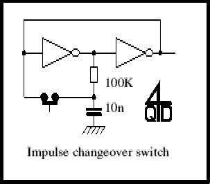
The circuit above shows a simple way of doing a switch using a couple of CMOS gates. Simple and reliable. But totally impractical in this application. CMOS was right out.

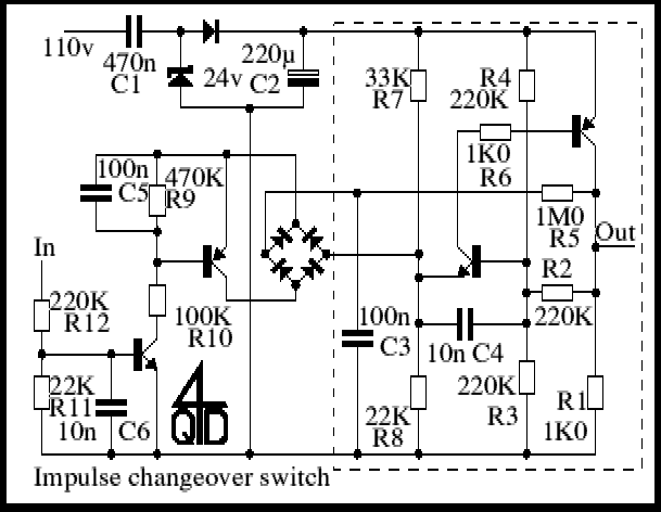
So I implemented a discrete transistor version of it. The part within the pecked box is the switch itself. Note the same resistor and capacitor (R5 & C3) between input and output, and the two input wires which, each time they are shorted, change the switch's state, The circuit is not an exact analog of the IC version.
The circuit used a capacitor dropper to work from the machine's 110v a.c. supply (remember it was to be a simple wire-in replacement for an existing relay). If you are using a capacitor dropper this must ba an X rated component. This means that they are safe for operation on a.c. mains and will not fail short circuit - which could be dangerous. Also - never play around with direct mains connections unless you know what you are doing and can do so safely.
R1 may be replaced with a relay. However if using a relay, make sure your poweer supply can deliver adequate current: using a capacitor for a mains dropper is OK for low current but for a significant current you need a large capacitor. A transformer is safer.
Note also the fact that the a.c. from the capacitor is fed direct to a zener diode. This conducts in one direction and goes into normal 24c zener operation on the other. So there is a 25v squarewave across is which is fed via the one diode to a reservoir capacitor (C2). A simple way if getting a regulated supply - it has a little ripple present. The actual operating voltage of the switch is not important: 12v to 36v will be OK with most common transistors.
R7 and R8 establish a reference voltage of about 10v (2/5 of the 24v supply). R4 and R3 feed 12v to the base of Tr3 but R2 is also present and shunts one or other of them so the actual voltage on the base will be 1/3 or 3/3 of the 24v rail - 8v or 16v. These two voltages are stable states so the circuit is stable with both transistors off or both on. C3 charges/discharges via R5 and, when it is at its full charge, instantaneously shorting it to the junction of R7/R8 puts a pulse on here which changes the circuits state but R5 is too high a value to have any effect so the circuit cannot re-change until C5 has changed charge again.
Since the switch must be bi-directional a diode bridge is used with a transistor across it. The two input transistors are decoupled to they are very insensitive to interference. The whole circuit worked fine and didn't mind the arc-start interference. It proved far more reliable (and a lot cheaper) that the old impulse relay.
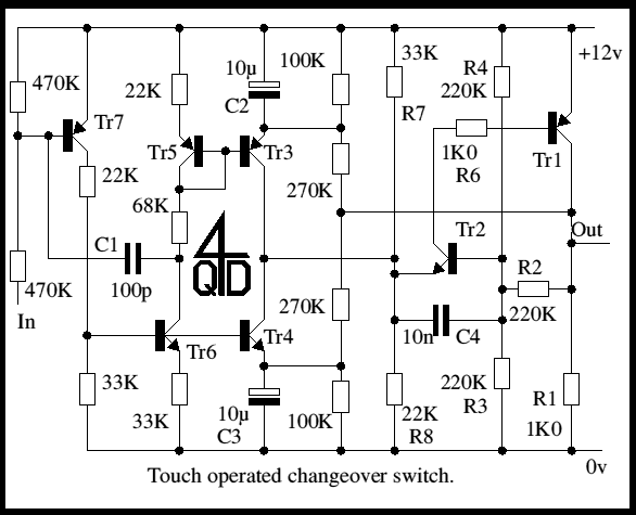
Now most electronic engineers recycle good circuits. The switch part of this was one I had used before in a touch operated switch to turn on and off our central heating, si I knew the circuit worked well. All I had to do was to change the operator. The circuit below shows the touch operated version.

The relationship between the two is fairly obvious but they use a slightly different style of operation. Touching the input feeds in hum and leakage which cause Tr7 to conduct, turning Tr6 on. There is positive feedback present to square up any hum and make the circuit mote sensitive.
Now Tr4 and Tr6 are arranged as a current source/mirror pair ( more about current sources and mirrors) as are Tr5 & Tr3. But the actual output current from Tr3 or Tr4 will depend on the state of the switch fed back via the two 270K resistors. Depending on this state one or other of Tr3/Tr4 will have a reverse biased emitter-base so the other one will conduce, changing the switch's state.
I hope you find the circuit unusual, useful and thought provoking. As usual any comments / queries / suggestions / corrections to the author.
| 4QD Sites: |