
|
4QD-TEC
|
|
This is a circuit thich I originally included in my book, 22 Tested Transistor Projects, published by Babani Press in 1976 (ISBN 0 900162 63 S). It is one I had great fun with. It uses the PUT Complimentary Feedback Pair as a sensitive detector of changing electric fields to switch on an oscillator and make a noise. It is so sensitive that it can be difficult to get it working on a test bench because of all the electric fields, but put it on a table and leave it. Then when you walk up to it, your movement is likely to cause enough field change to trigger it. Triggering not only depends on how fast you approach it but also on the clothes you are wearing, the relative humidity and your own body capacity and skin conductivity, so it reacts differently to different people. Some it reacts to not at all, others cannot even approach it.
In the original write-up, I even said that it appeared to be a male circuit as it tended to react more to women than to men. I haven't tested that and suspect it would not be true today. In the 70's women wore more nylon clothing than did men and antistatic fabrics were unknown.

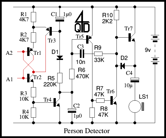
Tr1 and Tr2 are a PUT Complimentary Pair as explained on that circuit's page. Any charge difference between A1 and A2 causes a few electrons to flow into the transistor bases and they both turn on allowing current through R1-R2-R3-R4. Tr4 turns on, starting the oscillator and causing C1 to start charging. When C1 has charged enough (set by R1 and R2) Tr3 turns on and robs the current from Tr1's base, turning off the PUT pair.
When they turn off, Tr4 is no longer turned on bit it has already discharged C2, which now charges up by maintaining base current to the oscillator and as it charges the oscillator's frequency dies. This changing oscillator frequency actually causes a very interesting sound.
This voltage controlled oscillator consists of Tr 5 and Tr 6 with feedback via C3, R9. Initially with Tr4 off and C2 charged, Tr5 and Tr6 are both off and C3 is uncharged. When Tr4 turns on, Trs and Tr6 both conduct with additional current supplied to Tr6's base via C3 which starts to charge. When C3 is charged, there is just enough change in Tr5's collector current that a small signal is fed into Tr6 and the loop gain is high enough so that it starts to oscillate via the overall positive feedback.
Tr6 with Tr7 form a 'Totem-pole' output stage to drive a small loudspeaker. The original used a magnetic earpiece out of an old telephone handset, but these are maybe not obtainable. Any small loudspeaker should work.
You must take extreme care with building this circuit, at least with the front end, Tr1 and Tr2 collectors and bases and Tr4's collector: these are the bits attached to A1 and A2 and are marked in red. Ideally you should use two PTFE stand-off terminals for these and connect the three transistors to them in the air, not via a circuit board.
| 4QD Sites: |