Circuit 1
This is about the simplest current source possible. It is essentially an emitter follower where the transistor's Vbe is used to define the current through R2. If R2 is chosen so that the current through it is much more than the the transistor's base current, then ib can be ignored and the current through R3 (the load) is Vb/R2.
The same circuit is also used as a Vbe multiplier - when R3 is connected B-C of the transistor. As iR2 = iR3 the voltage between c-e is the transistor is Vbe x (R2+R3) / R2
Circuit 2
This is a very standard current source. Vin causes a current to flow through R1 into the diode. So a voltage is developed across the diode. This voltage is also present across the base-emitter junction of the transistor, so a current must flow in the transistor. The magnitude of the transistor current depends on the voltage developed across the diode and this is a function of its geometry. So the ratio of input to output current is not easy to calculate. However it will be pretty consistent with identical diodes and transistors because modern production causes very little spread in device parameters. The base-emitter junction of a transistor behaves just like a diode.
Circuit 3
Instead of a diode, you can use an LED. An LED (depending on colour, intensity etc) drops about 2v so you can calculate the output current as shown.
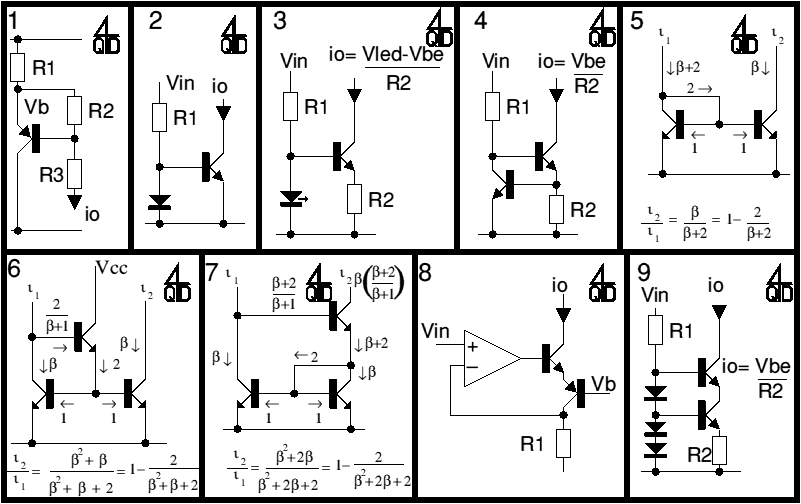
Circuit 4
This is a commonly used source: Vin drives current through R1 into the base of the second transistor, so current flows into the transistor's collector, through it and out of its emitter. This current must flow through R2. If the current gets too high, the first transistor turns on and robs the second transistor of base current, so its collector current can never exceed the value shown. This is an excellent way of either making a current source or of limiting the available current to a defined maximum value.
Circuit 5
This is a true current mirror: feed a current (i1) into the first transistor (usually by driving it via a resistor from a suitable voltage) and a 'mirror' current (i2) flows in the second transistor. Provided the two transistors are matched and of high gain, input and mirror current will match quite closely. In fact, with modern transistors, if you use a -C gain rating (450-900) matching of any two transistors is probably adequate for all usual needs.
Look at the equivalent circuit of virtually any analogue IC and you will notice this type of current source/mirror (it may be used for either) but it works just as well with discrete transistors.
One source of errors is if the voltage across the output transistor is high enough to cause the transistor to heat: the mirror's performance fails because the two transistors are now no longer well matched!
This circuit can also be used with resistors in both emitters - in this case the mirror ratio will depend on the ratio of these resistors. An example of this.
Circuit 6
This is for the purists: circuit 4 gives an error due to the base bias current. Here is the commonest way of reducing this error. It gives significantly improved performance.
Circuit 7
This is another way of reducing the error but this circuit is not quite so commonly known. If you calculate the formulae using practical transistors (beta = 500 or so) both 5 and 6 give very close matching - but 6 is slightly better. An example of this.
However there is a problem which sometimes occurs on current mirrors: if the output current is flowing from a significantly high voltage (Vc), then there may be enough power (Vc x i²) in the output transistor of figure 5 to cause the transistor to get warm: heating destroys the balance between the two transistors and so destroys the mirror's accuracy. In circuit 6 any heating is in the third transistor (at the top) and it is not part of the mirror so the mirror ratio is not affected by heating in this transistor. See 'Useful facts' below.
Circuit 8
Just to prove that I can use ICs, here is a current source (or a voltage to current converter) using an IC. You can use a single transistor (the PNP one) but the transistor's base current slightly alters the ratio. You can of course use an FET (zero gate current) but these are relatively expensive. Here is a complimentary long tailed pair biased to cancel out base current errors. Very good - provided you have a suitable bias point for Vb!
Circuit 9
One of the problems with circuits 2,3,4,5 and 6 is heating in the output transistor - a problem which was solved in circuit 7. Here's another way of avoiding heating causing an error - this circuit uses a cascode arrangement so that the current is defined in the bottom transistor, which has very little voltage across it. The top transistor has any high voltage across it, but heating in the top transistor doesn't affect the current, as it's the bottom transistor that is defining it.
Useful facts
There are two very useful figures that I remember about silicon diodes are to do with the change in voltage/current. If you increase the voltage across a diode by 60 millivolts, then the current through the diode increase by a factor of 10 - or vice versa. Try measuring the diode's drop when it has 100 microamps and 1 milliamp flowing: you will find the 60mV figure quite accurate.
The second figure is to do with the change in diode drop with temperature: increase the temperature by 1 degree K and the diode's voltage drops by 2 millivolts.
These figures hold for diodes and transistor base-emitter junctions.
Page Information
© 1997-2004 4QD-TEC
Page's Author: Richard John Torrens
Site hosted by Arachsys
Document URL:
Last modified:
