
|
4QD-TEC
|
|
In truth this, like many (most) VCAs is really a current controlled amplifier but there is really not too much difference since if you want to turn a CCA into a VCA you simply feed the current input from a voltage via a voltage to current converter (a.k.a. 'resistor').
There are a load of different ways of controlling gain: JFETS are common, Light dependant resistors are easy to use. There are magnetoresistors. You can also use almost any semiconductor.
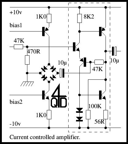
This one uses a diode bridge. This is possibly one of the oldest techniques so, perhaps, today one of the less usual - which should make it more interesting! The circuit is is two parts: the controlled amplifier, followed by the controlling circuit.

The first thing that may strike you is the absence of ICs. You may be getting the erroneous idea that the author doesn't like ICs! If you feel that way, then the good news is that the pecked box contains an operational amplifier (described elsewhere in this site). In fact the original circuit was designed around a CA301. This was back in 1977 when 'op amp' meant 741. The 301 was a great improvement in performance - but my four transistor circuit gave better performance than either! In any case - most people will learn more about basic electronics by using discrete components. The choice is yours.
The circuit is quite simple: the input is fed into a 100:1 attenuator (47K and 470R) to the non-inverting op-amp input. The feedback is via another 47K with the diode bridge forming the gain defining resistor from inverting input to 0v. The op-amp is fed from a split supply (10 - 0 - 10v or thereabouts).
Performance control range: The maximum range of the control is determined by the performance of the op-amp. If you are trying to get 60dB control range you need a good, low noise op-amp: the discrete one in the circuit is good enough to give 60dB range. 60dB range resulted by varying the diode bridge current over the range 1microamp to 5 milliamps. 40dB was given over a 35microamp to 5milliamp control range.The 301 of the original one was not quite so good. To get really good control range it may be necessary to match the diodes in the bridge.
Noise: for a good control range you will need a low noise op-amp. Low noise transistors can easily be used in the discrete transistor op-amp but there is a slight problem with low frequency noise caused by the Vbe offset charging the 10mu cap in the feedback circuit. With a high performance, low noise op-amp you should be able to get away without this capacitor. With the capacitor present you must not change the gain control quickly.Also for low noise you must closely match the diodes in the bridge.
Matching: the original circuit was tested with four stages such as you might use with surround sound. With a little bit of care the four amps can give a matching as close as 1dB over a 60dB range. Matching between amplifiers is controlled by matching of the control current sources - which leads us on to the next bit of the circuit....

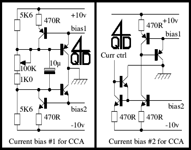
The second circuit is a biasing system: its two bias lines can control several gain stages. Essentially it is two complementary current mirrors controlled by a single potentiometer. You can get 40dB range from the amplifier without much trouble but you may need closely matched resistors for the two sources to get 60dB control range. It is not always convenient to control a set of gain stages from one potentiometer - you may wish to use a signal - the output of a previous stage for instance. Circuit 3 shows a way of doing it. The circuit is controlled by the input current via two sets of current mirrors. If you want to read more about current mirrors - there is a tutorial elsewhere on this site.
Both control stages should give good results but you may need to match positive and negative mirrors or you may get problems.
Expected performance. No guarantees here - the circuit was only prototyped, never produced in quantity but you should easily get a matching between stages of +/-1dB over 40dB range with 0.05% distortion and -55dB signal to noise ratio. Much will depend on the op-amp you use.
As usual let us know of any queries/complaints/suggestions/problems. We also like to hear if you find the circuit useful/interesting. Even if only to point out a spelling mistake - there are more browsers checking than could ever be duplicated by proof-reading! Enjoy it.
| 4QD Sites: |