
|
4QD-TEC
|
|
This is a circuit to use a standard, low quality opto isolator to transfer an analogue signal with reasonable linearity and without complicated feedback loops to monitor and linearise it.
The circuit was designed to interface a mains driven thryristor motor controller to low voltage analogue circuitry. In this application you could isolate the thyristor controller with a transformer and earth one side of the motor, but you still have a potentially high voltage situation if there is a wiring fault or component failure. Also motors and thyristor controllers are potentially good generators of noise: in a system which used several motor controllers it was considered essential to isolate the input signal!
Thyristor motor controllers, without lots of setting up and without tachogenerator feedback can give around 15:1 speed range. This isolator was certainly linear enough for this sort of application and performed very well in a production situation.
This is another circuit which has been produced and could be produced again if quantities are sufficient: 30-50 boards would be a suitable initial quantity.

It may be instructive to compare the first part of this circuit with the voltage controlled clock generator. You may notice a distinct resemblance in overall form.
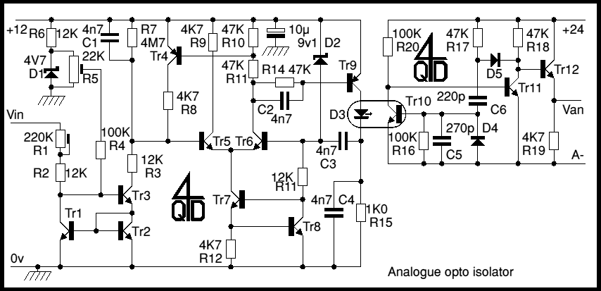
Tr1, Tr2 and Tr3 form a precision current mirror (see also Current sources and mirrors - a voltage applied to Vin causes current to flow through R1 and R2 giving rise to a 'mirror' current which is sinked into Tr3's collector.
Consider C1 (4n7) at first uncharged. The current sinked by the mirror changes it and the base of Tr5 falls. When the base voltage of Tr5 is near the positive line, Tr4 is conducting but when it falls to about 9.15v below the +ve line (voltage determined by D2), Tr5 starts to cut off and Tr6 starts to conduct. This will turn on Tr9, whose collector voltage is coupled back to Tr6's base via C3 to cause positive feedback so Tr9 turns hard on, drawing a pulse through C4 and the opto-coupled diode, D3.
During this pulse, R10 and R11 cause Tr4 to conduct, shorting out C1 and re-setting the relaxation oscillator.
The pulse in the opto coupler's transmitter causes its transistor to conduct. The original circuit worked very reliably on a cheap coupler such as 4N38. When the opto conducts, Tr11 turns off, D5 goes reversed biased and C6 charges up thorough R37, holding the opto coupler on for a defined pulse time. As soon as C6's current falls too low to maintain conduction, Tr11 turns on again, discharging C6 via D4,and D5. This discharge path is low impedance so discharges C6 very quickly. The circuit can therefore work with a very short time between pulses. Clearly, is the pulse is 90% of the duty cycle, the average voltage on Van is 95% of the supply voltage.
At low input voltages (into Vin) the oscillator charging current will be low and the opto pulses widely spaced. Tr11 will be conducting most of the time therefore and the average output voltage, Van, will be low. As the oscillator's frequency increases with increasing input voltage, pulses will be more frequent and the average output voltage will rise.
The voltage on Van is always a fixed pulse width at variable frequency: the motor controller it was used with had a ramp (as do pretty well all motor controllers) which averaged out this pulse train so the controller responded only to the average voltage.
| 4QD Sites: |