
|
4QD-TEC
|
|
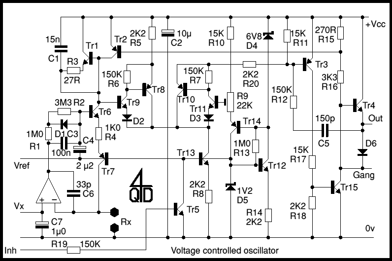
This is a voltage controller oscillator that was designed as a wide range oscillator to generate clock pulses for a stepper motor drive system. It does however have some interesting features. The original application used a stepper motor for its ability to operate over a very wide speed range, so this oscillator is also designed for a very wide frequency range. The prototype could be varied over 1,000,000:1 - six decades. Rather more than is easily accomplished with most VCOs. There are changes to the circuit which could extend even this range!
Since the oscillator is voltage controlled, it can also be used with a joystick via one of 4QD's Joystick Interface Boards. To facilitate this the oscillator includes not only an inhibit input but also a 'gang' input for coupling one or more clocks together.
In common with most other 'voltage controlled' oscillators, this circuit is really current controlled! It's also another of those cases (which I've so often encountered) where I've spent days scouring manufacturer's data books for a chip to do the required job, only to solve it in a few hours after I'd stopped looking for a ready made solution!
This is a circuit which has been in the past a production item, so is tried and tested. 4QD could therefore produce them, provided the quantity is reasonable. Since artwork has been prepared once, we could produce a quantity as small as 25-50.

Tr6, Tr7 and the IC form a precision current sink. The IC we used was a 3140 but any op-amp could be used, provided it is on the 'single supply' variety, i.e. one that will work with its input terminals at the battery -ve line. The 'output' current flows into Tr6's collector, through Tr6 and Tr7 and so Rx, which is connected external to the circuit board, so that it can be varied - e.g. to switch ranges. The voltage developed across Rx is compared in the op-amp with the input voltage Vx. Vx is obtained by a potential divider from the Vref line. So the current into Tr6 is very accurately Vx/Rx.
For stability, Vref is derived from D5 which is a 1v2 precision voltage reference. These have high stability and low drift. Of course, if you don't require these features, use, for instance, an ordinary LED to develop about 2v. The exact voltage is not important!
Tr6 and Tr7 form a complementary long-tailed pair (which I've described elsewhere) used as an output stage to the current sink. The basic circuit of this is described elsewhere (circuit 7) , here it incorporates a resistor (R4) between the emitters and a network between the two bases. This is to cause the frequency to change slowly if the current is switched: to operate a stepper motor at full speed the frequency has to be 'wound up' at a slow enough rate to allow the motor to accelerate. R4 and this network accomplishes this ramping.
The oscillator itself is a 'relaxation oscillator'. In this type of oscillator a capacitor is charged at a defined rate then, when it reaches a set threshold, it is quickly discharged to a lower threshold when the discharge circuit switches off and the capacitor again charges.
Here the charging capacitor is C1. It is charged by the current sink described above and discharged by Tr1/Tr2.
Since the top end of the capacitor is connected to +Vcc, charging it causes its lower end to fall towards 0v. The low end of this charge ramp is set up by the preset on the base of Tr11. Tr9, Tr8, Tr10 and Tr11 are a standard long-tailed pair with high gain and Tr13 as a constant current tail. This long tailed 'complimentary darlington' pair has extremely linear characteristics and will work at extremely low base currents, so even at very low frequencies will behave predictably without pulling the expected frequency much.
The preset, R9, is not very necessary but, on a production run, enabled all machines to be calibrated accurately, without using precision components, adjusting R9 simply alters the frequency.
D5 is also used as a base bias for Tr13, the tail for the long tailed pair and also to simply Vref, the voltage source for the input.
The output stage is a monostable pulse generator built around a totempole: Tr15 is the base of the totempole and Tr4 is the top. C5 with R12 determine the on time. While the output stage is on (output low), Tr2 is turned on, discharging C1.
This monostable is required because the stepper driver for which this was used had a defined minimum acceptable pulse width. However, since this pulse width is fixed and the time between pulses is variable, the current to frequency graph naturally becomes non linear as the pulse time starts to become significant compared with the ramp time.
Tr5 is an inhibit: when this is turned on, the whole circuit shuts down, drawing virtually no current. C1 will remain discharged. When the inhibit is released, C1 starts to charge, so the circuit always starts up from a defined state.
The discharge switch consists of Tr1 and Tr2. Tr1 was a TO5 transistor such as BC301, to handle the high discharge currents that I thought might sometime be required if C1 was drastically increased in size. With a 15n, the discharge current is not excessive, so the TO5 is an overkill!
The circuit is generally an overkill in many respects, but when initially designed I did not know what range of frequencies might eventually be required. So I added the extra transistor here and there because it improved potential performance. As it happens, much lesser stability and range would have been perfectly satisfactory.
The connection marked 'gang' was provided so that two such oscillators could be connected together. The faster oscillator will dominate and both will work in synchronism.
Much of the circuit is in fact a comparator made with discrete transistors. Indeed, there is no good reason why a comparator should not be used. However with the darlington arrangement shown, base current is quite tiny. For even smaller base current, the long-tailed pair could be exchanged for a pair of JFETs. Modern silicon transistors can work down to a new nanoamps, so the charge current can be quite tiny. How about increasing C1 and making an oscillator which pulses once a week! I'm not saying I ever got that low: I'm far too impatient to measure it!
I did design a PCB layout for this circuit: this board measured about 50mm x 100mm so is not huge. If this circuit is of use to any business so that it's worth making a batch, this could be arranged. The circuit has the benefits of having been produced in reasonable quantity and of being tried and tested over many years.
| 4QD Sites: |