
|
4QD-TEC
|
|
In principle it's easy to arrange an automatic switch-off system. The difficult bit is deciding exactly what condition should cause the system to switch itself off. So I suggest you think about that first - it's different for every system and not therefore something I can discuss here.
The second most difficult bit is deciding exactly what criterion you consider as being off. Most low voltage switches are likely to switch only the d.c. side of the supply so if it's mains operated, the transformer will still be on.
Then of course what's off will also depend on how you want to switch the system on. Off may have to be 'standby' where only part of the system is off, but some of it is still on, waiting for the correct on signal to arrive.
Probably the easiest way of doing automatic switch off is with relay logic.

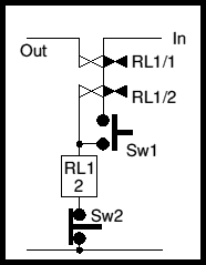
In the diagram, the box marked RL1 is the coil, the 2 in the coil box tells you there are two sets of contacts somewhere on the circuit, operated by this coil. In this simple circuit, it's easy to see them!
Sw1 is a momentary push switch. When it's pushed (contacts closed), voltage from In is applied to the coil so the relay operates. RL1/1 (the first set of contacts on RL1) closes and applies power to Out. RL1/2 closes at the same time and shorts out Sw1, maintaining power to the relay coil. So Sw1 is a push to switch on and the circuit is a relay bistable - bistable as it has two stable states, on and off.
Sw2 is a momentary push-to-break switch. Pushing it interrupts the current flowing through the coil of the relay, which promptly de-energises and the circuit switches off.
It's a very simple way of doing on off switching with two push-buttons and the contacts that open the relay current to switch it off can be expanded to any number of different contacts in series, opening any one of which will switch off the circuit. One contact can be a relay operated by whatever system you use to define that it's time for automatic power off.
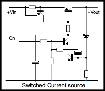
Exactly the same thing may be done with transistors. There are lots of ways of doing this type of switching and the diagram below shows but one

This system is the way many of 4QD's controllers are powered, though this particular circuit is most like that of the 4QD series. It is essentially a switched current source feeding a zener diode which acts as a stabilizer. The current though the zener is monitored by one of the transistors that switches the current source so that as the output voltage gets overloaded (so that the zener current falls to zero) the circuit switches itself off.
There is more information including a discussion and component values in the 4QD-TEC members area page
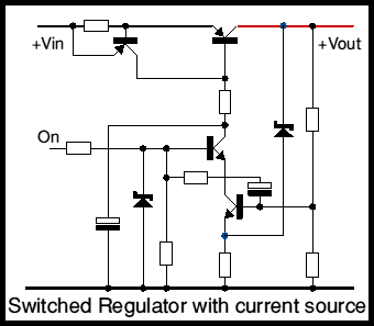
There is an article on site on two transistor regulator circuits. The third of these circuits is a bistable regulator. As often happens when thinking of one circuit, another idea pops into mind. The switching on and off arrangement in the above circuit can also apply to this regulator, and the circuit below illustrates this idea.

As in the above circuit, the series pass transistor is arranged as a current source: this is not always necessary. The regulating zener is here returned to the emitter of the transistor, which has a resistor present. This shuts off the current fed to the series pass transistor so that it conducts a variable amount to maintain the output voltage. The current source is then a current limit (which is why it can, optionally, be removed.
There is more information including a full discussion and component values in the 4QD-TEC members area page
| 4QD Sites: |