
This page discusses the various ways that a voltage regulator can be made using two transistors. If one of these transistors is the series-pass element, then the other must be the error amplifier, so there is a distinct limit to the number of possible circuits. If we also specify that we are only interested in regulators that control the positive supply, then there are only four basic configurations to discuss.
This may seem like a fairly sterile subject - but you may well be amazed at the implications and ramification.
| |
| Circuit 1 | Circuit 2 |
| |
| Circuit 3 | Circuit 4 |
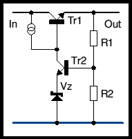
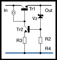
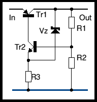
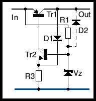
These are probably the most obvious of the four, to most readers. I guess really calling them two transistor circuits is possibly stretching things as they both show a current source to supply base current to the series-pass transistor. Yes, if conditions are right, you can use a resistor here.
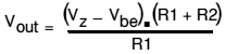
Circuit 1 has the reference zener in the emitter of the error amplifier. Circuit 2 has the reference zener in the base.
The voltage of circuit 1 will be
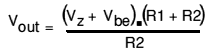
which may be less than useful as it relies on the value of the current source.
This is rather more interesting. However, consider the situation where there is no output voltage. Clearly in this case there can also be no voltage on the base of Tr2 which therefore cannot conduct. So the circuit is quite stable in the off state. It is in fact a 'bistable' - one stable state is off and the other is regulating with an output voltage of
Now this can be quite useful - if you want a tripped power supply. See Switched Power Supplies where this is the basis of the third circuit.
Notice also that the term (Vz-Vbe) occurs in the formula. If you chose the zener diode correctly, its temperature coefficient can broadly cancel out the tempco of the transistor and the output voltage will be better stabilised against ambient temperature changes.
Probably my favourite of the four. Here R1 is driven from the In voltage so that the zener is always biased - this removes the problem of the two stable states - on and off. But there's nothing to stop you biasing the zener from the output if you wish a trip!
No formula here as the output voltage if Vz, more or less. The emitter voltage of Tr2 will be Vbe less than Vz and the output will be stable one diode voltage above that.
Adding the extra diode D2 is interesting: with it present a re-entrant power supply can be built. See Simple regulated power supply with overcurrent trip for a practical circuit. In this, the circuit has been turned on its head, to stabilize the negative rail, so uses a PNP series pass instead of an NPN, and it also uses a Darlington transistor instead of the single pass transistor here, but it's the same configuration.