
|
4QD-TEC
|
|
We were asked to design an interface for a radio controlled golf caddy - a sort of golfer´s version of Robot Wars, we thought...
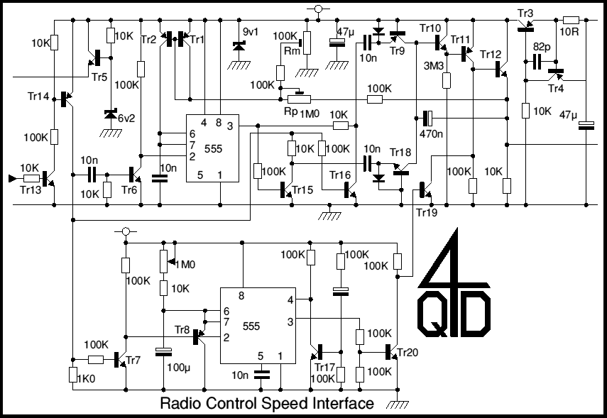
This is the circuitry that we evolved (and discarded!) for the interface. It is in two parts because of the mechanical design of the caddy. The first half is a speed interface which simply translates the standard radio control pulse width to an analogue voltage which is fed to one of 4QDs motor speed controllers. I know - the circuit looks too complicated for such a simple task, but it is in fact doing a few other tasks that the customer required.
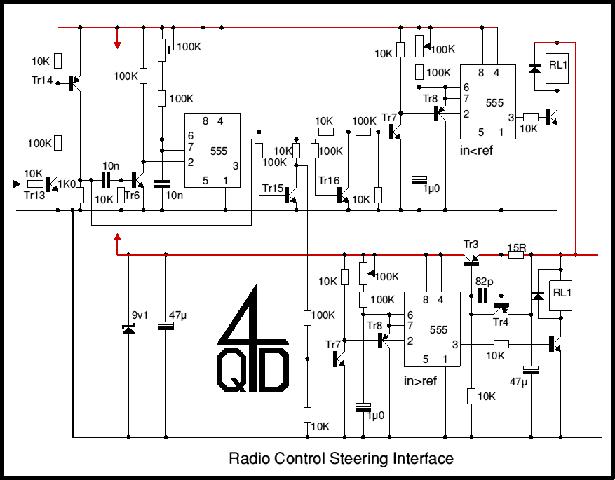
The second half controls the steering. The mechanical design is a 3 wheeled caddy with the ´single wheel´ actually a closely spaced pair of wheels which are driven by the main drive motor top provide motive power (this is the motor controlled by the first circuit). However the pair are on a motorised swivel arrangement: this second motor is the steering and can rotate the pair through 180 degrees, thus providing not only the steering but also the direction control.

Tr3 and Tr4 are a current source feeding a 9v1 zener to provide the internal supply. Tr5 with the 6v2 zener supply a 5.6 volt supply to the radio control receiver. This receiver gives two outputs - one is used for motor speed control and the other is used for the steering.
Tr13 and 14 are a level shifter and pulse conditioner to shape the radio receiver´s output pulse. The shaped pulse is fed to the pulse length detector consisting of the first 555 with Tr15 and Tr16. The 555 (which provides a reference pulse) is triggered by Tr6 on the positive edge of the input pulse. Tr15´s collector is high only when the input pulse is present and the 555 if off, so it gives a pulse output only if the input pulse length is longer than the reference pulse. Similarly Tr16´s collector is high only when the refernce pulse is present but there is nothing on the input pulse. This pulse indicates reference is longer than the input.
Tr10 and Tr11 are a ´pump and hold´ circuit. Tr11 is operating at 90 microamps (9v, 100K) maximum so its base current is around 1/3 microamp (assuming a gain around 250). This base current is supplied via the 3M3 resistor (which is actually feeding 3 microamps - more than enough).
So under worst case conditions Tr10 might have an emitter current of 3 microamps. Its base current is around 10 nano-amps. Assuming Tr9 and Tr18 are not conducting, this base current can only come from leakage - or the 470n capacitor. This gives a discharge rate on the capacitor of around 20 millivolts/second. We were after a hold time of around 30 second maximum and we considered a 600mV drift perfectly acceptable. It can easily be bettered by careful attention to detail and it if also possible to use a JFET to remove the base current.
So in the absence of any input pulse there is no reference pulse so no pulses at the two 10n capacitor. The 470n slowly charges from leakage and the output drifts towards zero volts. If an input pulse arrives the reference pulse is triggered. If the reference pulse is too short a positive pulse appears at the 10n capacitor feeding the emitter of Tr18. The 10n charges through the diode. When this pulse stops Tr15 turns on, discharging the 10n. As the diode is reverse biased the capacitor can only discharge from Tr18´s emitter. Tr18´s emitter current is also its collector current, so the discharge pulse discharges the 470n capacitor and the output voltage rises a little.
So in fact this section of the circuit is also an up/down staircase waveform generator with two separate inputs: one for up, one for down - the same circuit is also used in our elsewhere in this site.
The pulses are not individual but are trains of pulses: over a few pulses the output voltage changes significantly.
Now the reference pule generator (the 555) doesn´t have a conventional timing resistor but rather, a current mirror (more information on current mirrors). The charging current flows from Tr2´s collector and is equal to that flowing into Tr1. This input current has two components, a static part from Rm and a feedback component from the output via Rp. These two are adjustable and allow the pulse widths corresponding to maximum voltage (maximum pulse width) and minimum voltage (minimum pulse width) to be adjusted.
So we have a pulse width-to-voltage converter with a hold facility.
The bottom part of the circuit is a timeout function. Each positive going input pulse simultaneously triggers the timing cycle and clamps the timing capacitor to zero. So the timer output goes high at the start of the pulse train but only starts its timing cycle at the end of the last input pulse. If no more pulses arrive before timeout, the timer completes its time cycle and resets the output voltage to zero via Tr19 and the golf caddy stops dead.
If the logic of this is a little obscure, the idea is is to have a small hand-held transmitter with four buttons and a speed pot. One button is to be ´stop´ - the circuit for this is not included above but it will turn on Tr19, stopping the machine dead. Another button is ´refresh´. This will send a string of pulses (width determined by the speed pot) to set the speed. The idea is that the user pushes this every 30 seconds or so to send the caddy off, or to maintain its progress. If the operator doesn´t refresh the system in time, the timer times out.
The level shifter and pulse length comparators in the steering circuit are the same as in the speed circuit but the outputs are fed separately to two pulse train detectors. These are actually the same as the timeout in the speed control. While pulses are present, the timer´s output is high, activating the appropriate relay to turn the steering motor left or right.
The steering circuit is so similar to the speed control circuitry that there´s actually little to say about it!
Every designer sometimes wishes he´d started the project differently: this is no exception! The circuit actually works properly - but on the prototype the relays and motors cause interference to the receiver which tends to generate short output pulses. As you may imagine, these screw the operation up! So I´m going to have to put in a minimum pulse length filter of some sort....
It´s getting pretty obvious that this is getting too complicated as an analogue design - but it would go very well as software! So it looks like it´s time to start implementing it as a PIC or some other simple microcontroller!
Let me know if you do any more work based on this idea - who knows but we could be interested!

| 4QD Sites: |