
|
|
4QD-TEC
|
|
4QD manufacture PWM speed controllers for electric motors so you will hardly expect us to give you all our own unique circuitry and technical know-how, but there is much that is public domain and there are also ways of doing PWM that we have tried and rejected (for whatever reason). This page should give you a good idea of the principles involved and what to do - as well as what not to do!
This page is in fact the first in a long series on motor control, but the other pages are available only to 4QD-TEC members.
A commercial motor controller is more than simply a circuit to alter the speed of the motor and we have a 'guided tour' of controller features which explains simply most of the features incorporated into modern controllers and why they are needed.
To control the speed of a d.c. motor we need a variable voltage d.c. power source. However if you take a 12v motor and switch on the power to it, the motor will start to speed up: motors do not respond immediately so it will take a small time to reach full speed. If we switch the power off sometime before the motor reaches full speed, then the motor will start to slow down. If we switch the power on and off quickly enough, the motor will run at some speed part way between zero and full speed. This is exactly what a p.w.m. controller does: it switches the motor on in a series of pulses. To control the motor speed it varies (modulates) the width of the pulses - hence Pulse Width Modulation.
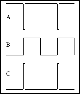
Consider the waveform above. If the motor is connected with one end to the battery positive and the other end to battery negative via a switch (MOSFET, power transistor or similar) then if the MOSFET is on for a short period and off for a long one, as in A above, the motor will only rotate slowly. At B the switch is on 50% and off 50%. At C the motor is on for most of the time and only off a short while, so the speed is near maximum. In a practical low voltage controller the switch opens and closes at 20kHz (20 thousand times per second). This is far too fast for the poor old motor to even realise it is being switched on and off: it thinks it is being fed from a pure d.c. voltage. It is also a frequency above the audible range so any noise emitted by the motor will be inaudible. It is also slow enough that MOSFETs can easily switch at this frequency. However the motor has inductance. Inductance does not like changes in current. If the motor is drawing any current then this current flows through the switch MOSFET when it is on - but where will it flow when the MOSFET switches off? Read on and find out!
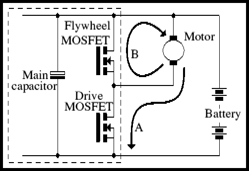
Consider the circuit above: this shows the drive MOSFET and the motor. When the drive MOSFET conducts, current flows from battery positive, through the motor and MOSFET (arrow A) and back to battery negative. When the MOSFET switches off the motor current keeps flowing because of the motor's inductance. There is a second MOSFET connected across the motor: MOSFETs act like diodes for reverse current, and this is reverse current through the MOSFET, so it conducts. You can use a MOSFET like this (short its gate to its source) or you can use a power diode. However a not so commonly understood fact about MOSFETs is that, when they are turned on, they conduct current in either direction. A conducting MOSFET is resistive to current in either direction and a conducting power MOSFET actually drops less voltage than a forward biased diode so the MOSFET needs less heatsinking and wastes less battery power.
You should see from the above that, if the drive MOSFET is on for a 50% duty cycle, motor voltage is 50% of battery voltage and, because battery current only flows when the MOSFET is on, battery current is only flowing for 50% of the time so the average battery current is only 50% of the motor current!
There is a problem however: when the MOSFET switches off, it not only interrupts the motor current but it also interrupts the current flowing from the battery. The wires from the battery have inductance (so does the battery) so when this current is interrupted this inductance causes a voltage spike: in the circuit the main capacitor absorbs (most of) this spike. When the drive MOSFET turns on again, battery current is asked to flow quickly - which it cannot. The main capacitor supplies current during the period battery current is re-establishing. In a controller capable of giving 120 amps this capacitor is working very hard and, if high current is drawn for too long (depending on the battery lead length) the main capacitor can explode! During the early development work we once used standard wire ended capacitors and melted the wires of the capacitor! Capacitors have copper plated steel leads and in motor control applications these leads can get extremely hot!
It will be apparent from the above that the work this capacitor does is extremely dependant on the loop inductance of the battery wires. Long wires will have a high inductance. Twisting the battery wires reduces their inductance.
It should go without saying that resistance in the battery leads will have an effect similar to inductance, so these wires should be thick.
Also, some people want to put an ammeter in the battery leads. The temptation should be resisted: simple car type ammeters in particular are highly inductive!
Simple controllers (such as are used for motorised golf bags) usually omit the expensive main capacitor and rely on the capacitance of the battery. You can get away with this - and the Eagle and Egret are such controllers. However a brief explanation of the effects are in order. To illustrate this, a graph of the battery voltage as it can be seen with an oscilloscope connected directly across the battery supply at the controller terminals. The scope earth is on the negative rail.
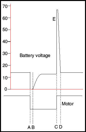 The top is a 'scope's eye view of battery positive, bottom is of the motor negative terminal (which is being switched by the controller). The waveforms have been cleaned up a lot to illustrate: in practise there is a lot of 'dirty' ringing on the waveform. The supply shown is 12v.
We join the waveform at a point where there is no battery current: the motor output is high and current is re-circulating in the flywheel. At A, the controller drive MOSFET switches on, diverting the motor current to flow from the battery. But the battery leads have inductance! The battery current cannot start immediately, so the battery leads drop a full 12v and the controller voltage extinguishes until the lead inductance can charge up, which it does by point B. The time A-B depends on current and battery loop inductance, and can be a significant proportion of cycle time!
Then, at point C, the bottom MOSFET turns sharply off, interrupting the current. Motor current is no problem, it keeps on flowing and the flywheel device is there to make sure it does! But you cannot suddenly stop the battery current - so it objects in the form of a large voltage spike. This spike rises until something gives: in this case it reaches the MOSFET avalanche breakdown voltage and the MOSFET clamps it. You can easily see the flat-topped clamping voltage with an oscilloscope. MOSFETs are rated for repeat avalanche energy and you have to be sure that the 1/2Li² stored in the battery loop inductance is well below the safe repeatable avalanche energy.
This is a problem: working out battery loop inductance is nigh on impossible - even for an engineer. For a punter to do it is - well, difficult. So a manufacturer simply supplies controllers to a known set of customers who use them in standard ways and sorts out problems as and when they arise on a empirical basis. It's always a question of a non-technical customer trying to get something for nothing: the main capacitor is needed. For some applications you can indeed get away without! But it is definitely 'getting away with it'!
In controllers with a main capacitor, most (but not all) of the supply irregularities are smoothed by the capacitor. Nevertheless you will see a positive overshoot and ringing as the battery current is interrupted.
Regenerative braking
You may prefer to return to this bit after you have studied the two circuits below. The 'very simple controller' does not include regen braking, the 'more sophisticated controller' does. This description needs to be read in conjunction with the second circuit, but also refers to the diagram above, so is inserted at this point to save you re-loading the diagram.
One of the well kept secrets of motor control seems to be regenerative braking. Yet it really is no secret: the circuits that give regen braking are not uncommon, yet few people seem to realize what happens. So here goes.
In the first circuit (above) is shown the output pair of MOSFETs, with the motor being driven. It has also been pointed out that, to the motor, the output from the controller is a pure d.c. voltage (because the motor's inductance keeps the current essentially constant during the switching cycle). Now the motor will generate a back e.m.f. which is proportional to its speed of rotation. At zero load this back e.m.f. will rise to be equal to the output from the controller.
We have already seen that the MOSFET is a bi-directional switch which conducts resistively (when it is turned on) for both directions of current. So consider the situation when the current is zero and the controller's output is now reduced. The motor's back e.m.f. is now higher than the controller's output voltage - so the motor will try and feed current back into the controller. If it succeeds in so doing the motor will be braked - we will have regenerative braking.
This type of circuit (where hi-side is turned on when the loside is off) is capable of sourcing current or sinking it. The way this works is that the reversed motor current is now a forward current to the flywheel MOSFET so when this is on it shorts out the motor - whose braking current rises during this period (arrow B, reversed). The Flywheel MOSFET now turns off, but this current must keep flowing - because of the motor's inductance. So it flows as reverse current through the drive MOSFET, recharging the battery as is does so. The extra voltage for this is derived from the energy stored in the motor's inductance. The process of switching from drive to braking is entirely automatic. Moreover it is done entirely by the motor's speed exceeding the drive voltage and without any change of state or switching within the controller. The regen braking is, if you like, a by-product of the design of the controller and almost a complete accident.
The circuit below is about the simplest motor controller. For the benefit of anyone who knows anything about motor controllers - 4QD did not design this circuit and we totally disown it, so feel free to laugh or cry in disbelief. If you decide to make it - yes, it works, but since we did not design it and don't like it - sorry, but you're on your own!
Nevertheless it is a circuit which we assembled at one time for a customer and we made several thousands! There are a lot of them still trundling around UK golf courses - so it does work! It also illustrates some of the things not to do!
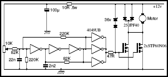
The first three sections of the 4049 are arranged, with overall feedback via the 220K resistor and a 22n capacitor on the input to give phase shift, as an oscillator. The output is a rectangular waveform which is buffered by the other three stages of the 4049 to drive the MOSFET gates. As the pot on the input is altered the average voltage on the 22n alters and this alters the mark-space ratio (the duty cycle) of the oscillator. With the pot at minimum the oscillator stops with its output low (i.e. the MOSFETs have no gate drive and are turned completely off) and with the pot at maximum the oscillator stops with its output high - the MOSFETs are turned on all the time. There are a few problems: firstly 'pulling' an oscillator like this varies its frequency. This doesn't affect the working too much except that if the frequency gets too high the MOSFETs switch on and off too quickly and get too hot. If it is too low the oscillator frequency becomes audible and the motors whine. The other problem is that it is virtually impossible to pull an oscillator so that it varies between a very high and a very low mark-space ratio! The 82K and 2n2 help in this respect by introducing negative feedback to reduce the gain in the positive feedback loop so the oscillator is only just oscillating: this is an addition 4QD made to the circuit and before this was done the controller had a nasty jump from 80% to 100% full speed. Note that the IC is a 4049UB (unbuffered) the buffered version will not work. Also certain makes of 4049UB do not work properly (anyone got a use for some surplus Toshiba 4049UBs?) because they are too good!
The other nasty thing is that the pot only varies the oscillator over about 1/3 of its usable range: this was OK in this application because the pot was used in a twist grip with only 90 degrees of travel! But it was necessary to adjust the handle to get the range correct.
So much for the oscillator/modulator. But hands up anyone who has noticed the absence of the main capacitor that I mentioned above. These are expensive components: golf caddies tend not to use them for that reason. What happens is that when the MOSFETS turn off the battery loop inductance causes a large voltage spike to build up across the drive MOSFET (which is turned off - remember that the motor current is now (mainly) flowing through the diode). But there is a 36v zener diode between battery positive and MOSFET gate. The voltage spike is present across this, so it conducts and the poor old MOSFET gets turned back on. In fact the zener limits the turn-off rate of the MOSFET to that required to sustain a 40v pulse. MOSFETs are very rugged devices and they will withstand this abuse (but there are more elegant ways of doing it). When the MOSFET turns on again, the battery tries to push current through the battery loop inductance - but cannot, so the voltage across the controller collapses in the attempt. But the MOSFET gate has voltage present and if there were no diode in series with the zener the zener would be forward biased, shorting the gate to the positive rail (now at zero voltage because of the collapsed supply).
Notice also the power diode as flyback. If you look at the specs on the STP60N06 and the 25JPF40 you will see that this is some overkill (brute force and a lot of ignorance) but this combination was arrived at by the customer simply by using a fatter device until he got no more failures! No finesse whatsoever! To add insult to injury, the controller had virtually no heatsinking and was housed in a plastic box. From an electronics designer's viewpoint there was very little right with the circuit - except that it worked and the customer was quite happy with it! I must admit that these are in fact the two most important criteria!
There also is nothing at all to limit the current flowing through the MOSFETs - except that the MOSFETs are 2 x 60 amp devices and the stalled motor current was about 60 amps.
A slightly more sophisticated controller
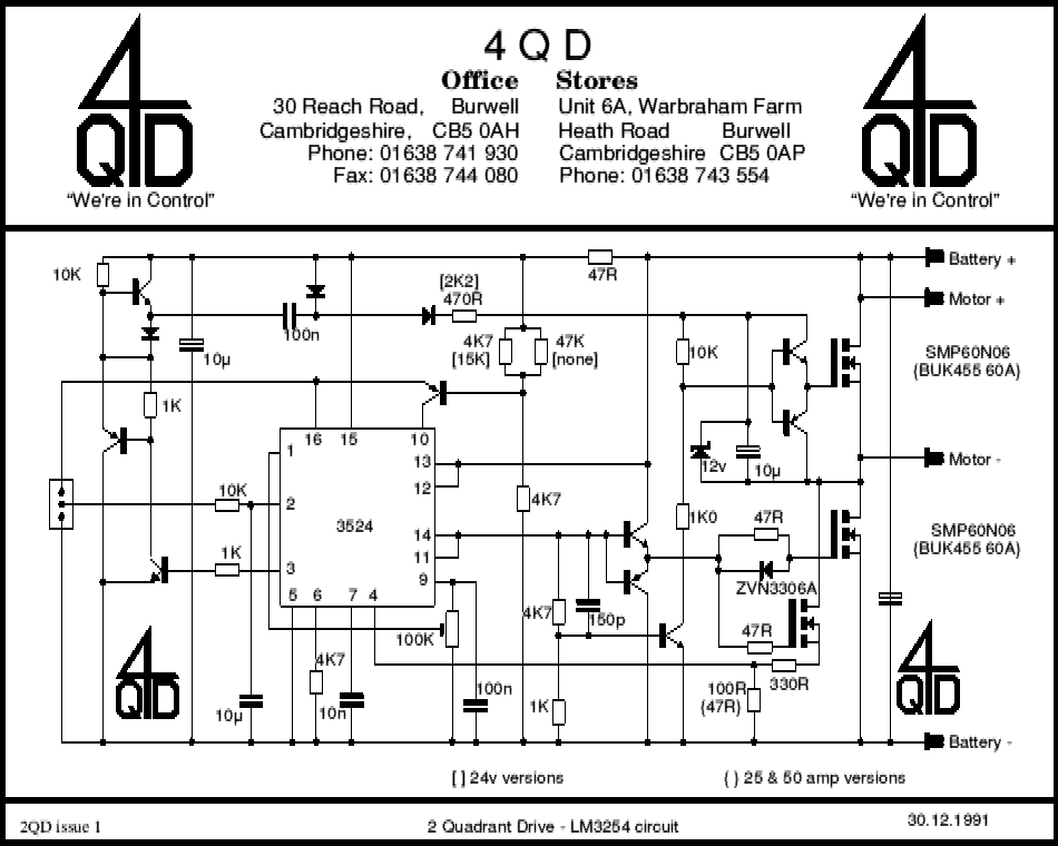
The circuit uses a 3524, a 'regulating pulse width modulator' so a brief description of the IC seems to be in order. The chip is aimed at power supplies and it has dual alternating outputs (pins 11 & 14) each of which can be on from 0% to 45% of the cycle time. But these outputs can be connected together as we have done here. Connected thus the output is a regular pwm output (as described at the top of this page) with a fixed frequency and an on time variable from 0% to 90%. Which, incidentally, is one of the chip's main shortcomings - a 90% on time means that you can only get 90% of full speed, not 100%. This is the main reason 4QD stopped using it.
The demand speed input from the slider of the pot is fed to pin 2. This is the input of a conventional op-amp, output from pin 9 and negative feedback is taken via a preset to pin 1: the preset then adjusts the gain. However this op-amp is unconventional in that its output is also connected to a second 'op-amp' in such a way that the second can over-ride the first and pull the its output down. The second then is used for current limiting. Its positive input is on pin 4 and its inverting input is pin 5 (which is connected to 0v).
The PWM output signal from the 3524 is fed to a pair of emitter followers to give adequate gate drive. The 47R gate resistors slow down the rise (switch-on) time and the diodes give fast switch-off. The 150pf also slows down the rise time. However this same 150pf also speeds up the switch off of the hi-side (flywheel) drive. Hiside should be turned on only when loside (drive) MOSFET is off and, ideally, there should be a small 'underlap' - a period during the switching (both on and off) when neither MOSFET has gate voltage. If both are on simultaneously a large punch-though current occurs which will cause heating and, in the extreme, could be destructive.
Because this uses the MOSFETs to sense their own current, it will accept a wide range of MOSFETs. However - it is designed for standard MOSFETs. The high side in particular is unlikely to work properly with logic level MOSFETs unless you change the values somewhat.
Be aware also that the MOSFET gates are driven from the battery line. It's an old circuit and when designed MOSFETs had a gate breakdown voltage of around 30v. With modern MOSFETs that voltage is getting lower and if you use a MOSFET with a 20v maximum gate voltage - running the drive from a 24v battery is likely to result in smoke!
To accomplish this, the 3524's oscillator output is used to drive a pump circuit. The 3 transistors at left amplify the oscillator to a squarewave which is fed to the 100n pump capacitor and to the two diodes in a voltage doubler configuration. The output of the doubler is fed to the 12v zener. Now, when the loside MOSFET is turned on, the bottom on this zener is connected to the negative supply rail so there would be a direct current path from +24, through both diodes and the zener. The 470R resistor in series with the pump diodes limits the current through this path.
This raises another point about hi-side pumps. As well as the voltage doubler there also exists a 'bootstrap' circuit. Ignore the pump circuit. When the loside MOSFET conducts, the zener (as we have seen) will have current flowing through it so the capacitor across the zener will charge up. When the hi-side switches on, this capacitor will retain this charge which will supply the hi-side gate drive. We therefore don't really need the pump circuit. The hiside supply on this capacitor will decay when the output stops switching with the lo-side switched off. This is at very slow motor speeds as (or after) the motor stops so the lack of drive is not a problem. The only reason the 2QD has the hiside pump is that is is possible to use two of them back-to-back in a bridge configuration. In this particular configuration the hiside drive must not collapse when the output stops switching.
This feature is actually not as necessary as some people think: with every 'feature' such as this, there are trade-offs. See our Guide Tour of Controller features for more.
Although this circuit works, and is a practical controller, there are several shortcomings. We are not going into details here, but almost all of these are explained and remedies given to members of The Electronics Club but if you want to learn how, you will need to subscribe to 4QD-TEC, see foot of this page.
PWM and motor Heating
A popular 'old wife's tale' is that PWM causes the motor to heat more than pure d.c. Like most old wives' tales, this springs from a partial truth nurtured by misunderstanding. The 'myth' comes about because, if the frequency is too low, the current is discontinuous (or at least variable over the pwm waveform) because the motor's inductance cannot maintain the current properly during the off period of the waveform. So the motor current will be pulsed - not continuous. The average current will determine the torque but heating will be an integral of the current squared (heating is proportional to I²R)- the 'form factor' of the current will be greater than unity. The lower the frequency, the higher the ripple current and the greater the heating.
So consider an oversimplified case where the current is either on or off. If the current flows for, say, 1/3 of the time and you require a torque from the motor equivalent to that given by 1 amp continuous, them you clearly need an average current of 1 amp. To do this with a 33% duty cycle you must have 3 amps (the current flows for for 1/3 of the time).
Now a current of 3 amps will give 9 times (I squared) the heating effect of 1 amp continuous.
But if 3 amps is flowing for only 1/3 the total time - so the heating in the motor is 9 times for 1/3 the time - or a factor of 3 greater than the steady 1 amp! This waveform is said to have a 'form-factor' of 3 (or is it 33% - no doubt someone will put me right!)
However - if the pulse repetition frequency is high enough, the motor's inductance will cause a flywheel effect and the current will become stable. For instance the Lynch motor has an inductance of only 39 microhenrys (being one of the lowest inductance motors I know of) and a resistance of 0.016 Ohms. The 'Time constant' for an L-R circuit is L/R which (for the Lynch motor) gives 2.4 mSec. For an SEM DPM40P4 (1kW) the inductance is 200 microhenries and the resistance 40 milliohms - giving a time constant of 5mSec.
As a rule of thumb and to avoid too much maths, the pulse repetition period must be significantly shorter than the motor's time constant.
Other factors that affects PRF are:
If is it is in the audio band the motor can emit a whine (caused by a phenomenon known as 'magnetostriction', so keep above the audio band.
A MOSFET circuit dissipates most while switching from one state to the other so the frequency should not be too high - MOSFETs can be used upto 100kHz with care, but this is getting a bit high.
RF emissions: these increase with increasing frequency, so keep the frequency as low as possible!
It is clearly difficult to chose a 'best' compromise between these but an optimum frequency would seem to be around 20kHz.
Obviously this script only covers a little of the technology involved: have a look at the specification of our Pro-120. This has linear acceleration and deceleration ramps, over-discharge limiting, high pedal lockout, dual-ramp reversing, regen current limit, reverse polarity protection as well as all the points mentioned herein. We also quote 110 amps for 1 minute: the real truth is that we get about 120 amps for one minute. We also know of no 'fair' way of destroying it: even shorting the motor out won't blow it. Reversing at full speed is safe. Reversing the battery is safe. Disconnecting the battery at full speed is safe (for the controller - but don't expect it to brake the machine). Then we have tried to protect it against all the things that non-technical customers may do to it. We think we have succeeded - until of course we find a customer who is cleverer than we are! Even if I was prepared to try, there is to way I could put into words all the experience needed to design such a controller - let alone to make a profit from selling it at the price we do. If you don't believe that then try asking the one off price of any similar controller.
All these pages are in the Members Private area.
PWM Part 2 Deals with early 2QD circuits. Includes circuit diagram and description.
PWM Part 3 Development of 2QD series. Later circuit and changes in detail.
PWM Part 4 Modern 2QD series. Detailed discussion. Includes
| 4QD Sites: |