
|
4QD-TEC
|
|
This page is a 4QD-TEC public area page. At the bottom TEC members can request additional data on this subject.
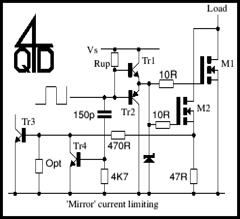
The circuit shows the method of 'mirror' current sensing a MOSFET. A fully conducting MOSFET is resistive and behaves exactly as a resistor. It therefore you limit the voltage across the MOSFET when it is conducting you automatically limit the current flowing through it. In addition the MOSFET''s on resistance has a positive temperature coefficient so as it warms up, keeping the voltage across it limited will automatically reduce the limited current flowing through it, keeping it within its safe region over a wide range of junction temperatures.

M1 is the main power MOSFET being sensed, M2 is a small signal MOSFET which performs the sensing. Tr1 and Tr2 are the gate drive transistors. When the gate drive is low, M1 and M2 both are off and there is then no voltage present across M2's 47R source resistor. When the gate is high, both MOSFETs are on so any voltage developed across M1 (by virtue of current flowing through it) will be transferred to M2's source resistor since there is virtually no current in M2 itself.
There is a problem during the period when the two MOSFETs are turning on: the turn-on time is usually controlled deliberately and during this time there can be a high voltage across the MOSFET as well as a high current through it. This turn-on signal must not be transferred to the sensing circuit as it is a transient state and not what we need to sense.
In this example the turn on time is controlled by the 150pF capacitor charging up from the base drive pull-up impedance, shown as Rup. This charging current flows into the base of Tr4, holding it on during the switching time. In fact Tr4 won't turn off until after the switching because of its base storage charge.
When the MOSFET has settled to its steady state, Tr4 turns off and the sensed voltage is fed to Tr3. If the sensed voltage is more than Tr3's Vbe it turns on, indicating over-current. Vbe multiplication can be done by fitting Ropt. Of course, there's no reason to use a transistor as a sensor - it could just as easily be a comparator or an opamp, which gives much better adjustability of the sensing level.
Although this gives you a signal showing overcurrent the real trick is knowing what to do with it next.
4QD use this MOSFET mirror method in one of our circuits (the 4QD series) but we have developed another method which does not use a relatively expensive MOSFET and which uses a comparator to overcome Vbe sensing level limitation.
Available to TEC members is a Library page of MOSFET Current sensing circuits. These include:
| 4QD Sites: |