|
|
4QD-TEC
|
|
All inductive devices, operating in d.c. circuitry, which are switched on and off (whether by a contact or by electronic circuitry) should have a diode connected across their coils to catch the inductive fly back.
This page explains why.
A coil (of any sort) is an inductor. Inductors behave to electricity as mass does to a mechanical system. Inductors resist change in current flow, just as masses resists change in physical movement. Stand in front of a moving car and try to stop it: its mass keeps it going.
In the same way, if you suddenly try to stop the current flowing in an inductor - the inductor will resist the change in current. The same way the mass of the car resisted the mechanical stopping, so will the inductance of the coil resist the stopping of the electrical movement - the current flow.
When the car hits an object - the momentum is changed into pressure. In the electrical system, the electrical (current) flow also is turned into electrical pressure - a huge voltage develops in an attempt to keep the current flowing. This voltage will cause an arc across the switch that is interrupting the current. This will eventually burn the switch, but in the short term, it causes electrical noise, which can have all sorts of effects, such as making electronic equipment misbehave - or even fail.
Clearly, what we need is some way of interrupting the current flow slowly - a method of letting the current die away slowly. Fortunately there is indeed an easy way to do this.
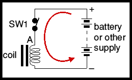
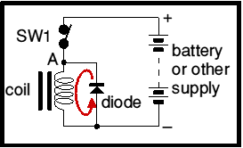
Consider the diagram to the right. It shows a coil (maybe a relay coil) and a switch connected in series with a battery. When the switch is closed, current will flow and the coil will energise. When the switch is opened, the current will stop and the coil will de-energise. But life is not that simple!
The drawing below shows how the current and voltage vary with time. At the first red line the switch is closed to energise the relay. At the second, it is opened to de-energise the relay.
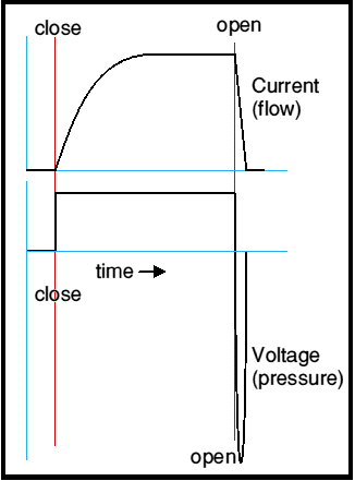
When the switch is closed, voltage is immediately applied to the coil. But because the coil has inductance, the current must be 'pushed' before there is any flow - your engine must push the mass of the car to build up speed (flow). So it is with the coil, current builds up relatively slowly, until eventually it has risen to the steady state value defined by the voltage and the coil's resistance.
When the switch is opened, current simply cannot keep flowing. But the inductance of the coil says that it must. Inductance makes it impossible to stop current immediately. So the inductor kicks furiously and creates a large enough spike in the voltage to keep the current going! Notice that this is a negative spike, so adds to the battery voltage, creating a large surge voltage across the switch. This voltage spike will cause an arc across the switch. It will also cause energy to be radiated as electromagnetic noise - a radio interference spike.
The energy stored in a coil is 1/2Li2, where L is the coil's inductance in Henries, and i is the current on amperes. The energy is in Joules and, for something like an industrial mains contactor - it can be quite significant. If the switch arcs, this energy is then dissipated as heat in the arc and it is this heat which causes the switch contacts to be burned!
With a catching diode connected as right, the spike does not occur: any voltage overshoot forward biases the diode and simply causes the current to recirculate in the coil.
We now have a coil full of stored inductive energy in series with a diode and it own series resistance. The current will decay with a time constant of L/R where L is the coil's inductance and R is the coil's resistance.
The drawing below shows the corresponding waveforms.
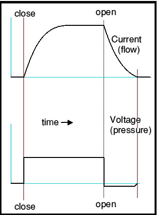
Notice how the spike, that was, is no longer present - but instead the current takes a long time to decay. During the time it is still flowing, there is a 0.6v 'hump' in the voltage - the 0.6v is the forward conduction voltage of the flywheel diode, which is of course conducting during this period.
Since the current takes a long time now to die, the relay or contactor or whatever also takes a long time to de-energise. That may not be desirable. However it is possible to tailor it. With no flywheel diode, deenergising is very fast. No flywheel diode is the same as a flywheel diode in series with a very large value resistor, With only a diode and a zero value resistor, de-energising is slow. So, presumably if we choose the resistor in series with the diode correctly, we can make the release time whatever we require.
This is quite true: relays take a time to energise and they also take a time to de-energise. It seems to me that in most cases the optimum release time is about the same time as it takes the relay to energise. You will get that sort of timing by putting in series with the flywheel diode, a resistor if value equal to the coil resistance.
Machine wiring: Good and Bad practises
Modular Relay System discusses this in the second part, for TEC members only.
PWM motor speed control discusses flywheel diodes: a parallel situation.
| 4QD Sites: |