
|
|
4QD-TEC
|
|
These ultrasonic circuits are all quite old: my notes date them at mid-70s so they don't use ICs. Nevertheless there are several places where an op-amp would possibly simplify things. Despite their age I hope they are of interest: certainly basic principles don't change.
This transmitter is designed to work with the next circuit as a remote control transmitter/receiver. It is only a single channel and you could once get multi-channel chips for the whole job. However ultrasonics have fallen out of favour commercially so I think most of these chips are now obsolete.
This is a fairly commonly published self-oscillating driver for ceramic (piezo) resonators. However with some resonators it can be a bit temperamental: the 1n0 capacitor across the top transistor of the totem-pole helps it to start up. Some resonators won't need this.
Also, the impedance curve of a piezo device is very complex and I found that some of them resonated at the wrong frequency (too low). A 1n0 cap in series with the resonator cured this - this cap is not shown here.
The two transistors to the left are a conventional multivibrator oscillating at 480hZ to modulate the transmitter. If I re-designed the circuit today I would use a 555 here as the old multivibs used to have problems starting sometimes. Use of the asymmetrical resistors and capacitors values helps this.
This is the matching receiver. You should note that the circuit easily divides into 3 stages (each two transistors) with a final transistor driving the relay.
Stage 1 is the preamplifier: it is a fairly conventional circuit with gain fixed by feedback.
Stage 2 is a second amplifier: you may notice a Wein network formed by the input and feedback into the base of Tr3. This tunes the response to around 40kHz.
The output from the second stage is rectified and fed to the third stage which is tuned to the modulating frequency by a twin-T feedback network. This picks out the modulating frequency. The output from the third stage is fed to the relay driver which is arranged as a rectifier so it stays on when the modulation frequency is present. Note the presence of a 25µ capacitor and the absence of a flywheel diode on the relay: this is another way of removing the switching spikes. It works pretty well - as long as you don't require fast relay switching since each time the relay operates the transistor has to discharge the capacitor which (if you don't get the values right) can cause a large current surge in the transistor.
The next circuit is an ultrasonic intruder detector. It uses Doppler shift from a moving object. Ultrasonics aren't used much for this commercially as they can be a bit temperamental to set up and tend to detect cats and curtains moving in a draft. Modern detectors tend to use a narrow beam microwave system which only scans a small area such as a doorway. Ultrasonics tend to scan the whole room.
The transmitter circuit is similar to that already shown. Not identical (I think I did this one first - but it was long ago). The preamp (Tr5 & 6) the same as the one in the receiver, but with different values (both work - you can always recalculate values starting with a different initial point and they'll both work).
Tr7 takes the received signal and combines it with the transmitter's signal to get a beat frequency. This is fed via a sensitivity control and Tr8 to a rectifier stage and a threshold detector. This turns on the relay once the beats exceed a preset level. This detector is latched so the relay remains on as is required for an intruder detector.
The next circuit shows how an ordinary diode can be used as a variable resistance element to incorporate automatic gain control.
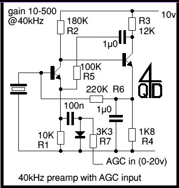
The last circuit is an ultrasonic preamp with a twin T feedback to make it highly tuned.
At the time I did these circuits I was writing a series of projects up for the British edition of Popular Science. The magazine folded after only a short run. One of the circuits (the intruder detector, I believe) was published in the last edition but none of them were really much more than experimental so never got sustained testing. Nevertheless they should prove interesting and I hope you enjoy them.
| 4QD Sites: |