
|
4QD-TEC
|
|

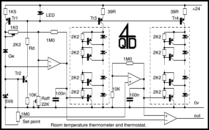
This is a fun circuit which is also something useful: I had this working for several years as a room temperature thermometer and thermostat to control the central heating. It has a germanium diode to sense the temperature, a line of LEDs acting as a thermometer and a second line of LEDs to show the 'set point'. When the actual temperature display passes the 'set point' display, the thermostat switches.
The reverse leakage current in a diode is a very strong and linear function of temperature. Unfortunately the leakage in a normal silicon diode is so small you can forget it. However a germanium diode is another matter entirely. This circuit uses a germanium diode (marked Ge) as a temperature sensor. I used an OA90 diode but others should do. The 'ring' of Tr1 and Tr2 bias each other. Tr1's collector current is stabilized by the 5v6 zener, causing Tr2 to operate at about 5mA: this collector current flows through the LED to generate about 1.5v bias for Tr1 so the current through the Ge diode is stabilized. The voltage across the diode will depend on its leakage current and you may need to alter the 1K5 to get a sensible range with a different diode.
The voltage across the diode is inverted by the first 'op-amp' (in fact one section of an LM339 comparator used as an op-amp) to drive the LED line, shown in the pecked box. This LED line has been explained elsewhere on 4QD's pages, but it is biased at constant current by Tr3.
There is one slight problem with GE diodes: although the leakage any diode has a very linear slope with temperature, it is very difficult to find two diodes with the same slope. That means you need to calibrate for range and slope. Rd adjusts the slope, i.e. the number of degrees per LED and Roff adjusts the offset, i.e. the centre of the range. The thermometer can be set to be quite sensitive, 0.5 degrees per LED if you wish.
The second LED line and op-amp duplicates the first. I used this to show the set-point. Adjusting the 'Setpoint' preset makes the illumination of the second line rise and fall. The third comparator senses the two LED line drive voltages and changes state when they cross. So you get an indication of the actual temperature, and the set temperature and an output when the set is reached.
The whole circuit worked from a 24v supply: remember that a standard red LED needs about 1.6 volts so the ten LEDs that I used (I've shown the top and bottom pair) need about 16 volts.
Enjoy it!
| 4QD Sites: |