
|
|
4QD-TEC
|
|
I guess every designer has circuits which are real flashes of inspiration. This is one such and, if there are circuits which I feel I should have patented, this certainly would be one of them! It is more sophisticated than its 14 components would suggest.
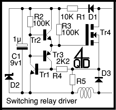
In the welding industry, one common weld power source is a 'drooper'. These start off with a high open circuit voltage, maybe as high as 125v and the voltage drops heavily down when on load, maybe to 20 or 24v. The requirement was to operate a 12v relay from such a drooper. This is the resultant circuit.
This same circuit was also very successfully used as a current source to supply low voltage control circuitry from the same drooper. A toroidal inductor was used with the load connected in series with ot, flywheel diode connected so that drive and flywheel current both flowed through the load. The load voltage was regulated with a zener diode.
I have used this circuit in several guises so it could be economical for 4QD to produce in relatively small quantities, say 25-50. Please contact us if you are interested.
It operates by PWM - well, actually by PFM - Pulse Frequency Modulation.
At power up, C1 charges up via D1 and R1. R2 will conduct, pulling the base of the emitter follower, Tr2, up and feeding gate voltage to the MOSFET. Tr4. Clearly the circuits in an analogue region during power-up, but as this is intended for use on a high voltage supply, power-up is pretty quick.
As Tr4 conducts, current is fed through R5 and the coil of the Solenoid. The current builds up, until the voltage across R5 becomes high enough to turn on Tr1.
Tr1 and Tr3 are a complementary feedback pair, so when Tr1 conducts, they turn each other on in a snap action switch and the MOSFET gate gets turned hard off.
The current in the solenoid coil is forced (by the inductance) to keep flowing. It does so via D3 and R4.
But the current into Tr1's base is the sum of the currents through R4 and Tr3. R2's current flows through Tr1, so none flows in Tr2, so Tr3 current (after the bate has discharged) is only the current through R3. So the current through R5 must drop by this amount before it is insufficient to keep Tr1 conducting. This current is caused by the sensed relay current flowing through R5, so the ratio of R3 to R4 sets the hysteresis.
When there is insufficient current to keep Tr1 conducting, it turns off and the gate is again pulled high by R5 and Tr2, turning the MOSFET on. It slams the supply voltage across the relay coil, building up the current. Clearly the rate of current build-up will depend on the supply voltage, so at low voltages, the MOSFET turns on for a longer time and at high voltages, a shorter time.
The time during which the MOSFET is off is dependant on the relay coil and is constant, whilst the on time varies, altering the frequency.
These things are all operating condition related, so I'll have to leave them to you!
The circuit, in production, proved to be very reliable. Clearly you need to watch voltage spikes and current ratings. You should also not try to operate it at low voltages, say less that the solenoid voltage plus 15v, as the MOSFET goes into linear mode. This is not immediately damaging to the MOSFET, but it can get hot. For this reason, it is probably best not to switch the re;ay by connecting and disconnecting the power, but by activating and deactivating the controller. Methods of doing this could be added later.
I have several variations and additions to this circuit. For instance, it's possible to switch it on/off via an opto-coupler if you want low-side switching. It's also possible to have a two current level version, where solenoid current starts off at a high value for pull-in, and drops to a lower holding current after a time.
| 4QD Sites: |