
|
|
4QD-TEC
|
|
There are dozens, probably hundreds of circuits for audio sinewave generators but certain 'old chestnuts' are still favourite and the basic circuits haven't changed significantly since they were built with valves.
There is one 'favourite' circuit for making an audio oscillator the Wien bridge. It is a bridge, i.e. a circuit having four 'legs'. The circuit below shows the basic idea.
The Rx, 2Rx feedback divider establishes a gain of 3 in the op amp. Positive feedback is via the Wien network, R and C (two of each). The characteristic of this network is that the network's output (at the +ve input to the opamp) has a maximum at a frequency Fo, as shown on the diagram. The mathematical analysis of any network tends to simplify itself if resistors/capacitors are related to each other by some simple ratio: with the Wien network the maths come out best if the two resistors are equal and so are the two capacitors! Hence the simple formula for Fo.
So, for 1kHz put, 1000 into the formula in place of Fo, choose a sensible value for R - let's chose 100K. swap the formula round to read C= 1/(2 x PI x 1000 x 100,000) and C works out to be 1.59nF: This is not a particularly sensible value for a capacitor but if we increase the capacitor we need to decrease the resistor and vice versa, so we can now chose a sensible capacitor: how about 4n7?
Putting 4n7 in the formula and rearranging gives R=1/(2 x PI x 1000 x 4.7 x 10-9). We get 33.9K for the resistors. At this point you need to decide how accurately you want 1kHz. Most Wien bridge circuits tend to be variable frequency, so we simply calibrate the scale to suit!
Because the Wien circuit attenuates the input by 3 times, we need a gain of 3 in the amplifier to make it oscillate. This was why we chose the 2Rx/Rx negative feedback.
There is one slight problem: is the feedback resistors define a gain of slightly less than 3, then the circuit won't oscillate. It the gain is slightly more than 3 the circuit will oscillate and the amplitude will only be determined by the IC's output hitting the supply rails and clipping - not a sinusoidal waveform. So how do we keep the gain at exactly the right level to just sustain a sinewave? What we need is some component which has a resistance proportional to the signal level: if the level increases, so does the resistance, putting down the gain. Similarly if the output drops, the gain will increase, maintaining stability. Fortunately there are several ways of doing this.
The second circuit is a practical implementation of a Wien oscillator but in this the Wien network is inverted. It is the 'wrong way up' and in the negative feedback path. Positive feedback is applied via the 500R preset to make it oscillate. And there's a nice incandescent light bulb to show that it's working....
You see, light bulbs get hot and the resistance of a piece of wire goes up as it gets hot. A bulb filament gets very hot so its resistance can change quite a lot (typically the hot resistance can be 10 times the cold resistance) and the higher the voltage, the higher the resistance, so this is the stabilizing element that we require! Quite a simple circuit which will give about 1.5v rms output with a distortion of about 0.3%. Not excellent performance but certainly useful - and such a simple circuit. Of course you can use an op-amp to do this - as long as it can give enough current to drive the bulb. But the circuit with 2 transistors is actually simpler.
The next circuit (above) is a better implementation of the Wien circuit: this uses the Wien in the normal fashion, in the positive feedback path and with negative feedback to maintain stability. The device marked Th1 is a glass bead type thermistor: some of these thermistors consist of a bead in an evacuated glass envelope and they are designed specifically for amplitude stabilization in such circuits. If necessary the 100R can be altered to suit various thermistors (and to trim the amplitude).
The 6 transistor circuit is, in effect, an op-amp and there is no reason you can't simply use an op-amp. This circuit pre-dates op-amps but the principles haven't changed.
A dual ganged 100K (logarithmic) pot is used to vary the frequency and a 2 pole 6 way (rotary) switch is used to switch bands. With the values shown there is a useful overlap at the ends of each band. With the pot set at around 16K the 10n gives 1kHz so the 'center' frequencies with the values shown are 100hZ, 300Hz, 1kh, 3kHz, 10kHz and 30kHz.
You could increase the range at the bottom with another capacitor (1µ) but settling time will be very long. Similarly you could add another range at the top using (100pf) but the waveform will not be very good: the high frequency end is restricted by the 270pF capacitor which is present to ensure stability: with as good layout and modern transistors you could reduce this capacitor significantly to increase high frequency performance.
A circuit such as this can give extremely low distortion if properly built. The distortion level will depend on the gain of the op-amp used and on the performance of the thermistor, especially at low frequencies. For audio test purposes, low hum and noise are also important so low noise components and a good power supply are essential.
The next circuit doesn't use a Wien network but a circuit called a twin-T network so I will introduce the network first. The 'standard' twin T is as in the diagram below.
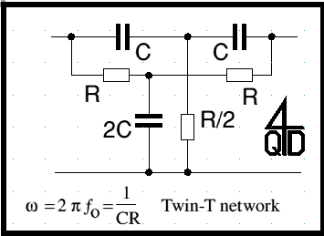
As with the Wien there is a relationship in the circuit that causes a simplification of the formula - the arms of the T should have equal values and the capacitor in the foot should be twice as large as the arms. The foot's resistor should be half that of the arms. With these ratios the Twin T is a notch filter which passes everything except for a notch at the centre frequency as shown in the formula. Note that this formula is the same as for the Wien but is shown in a slightly different form. So - now to
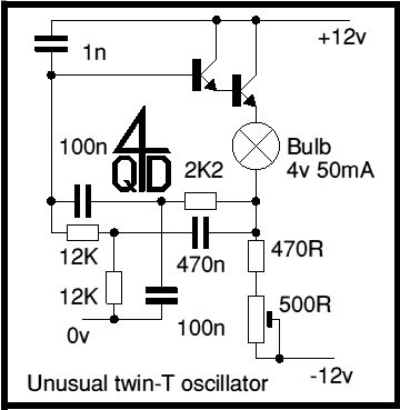
Perhaps the first thing that will strike you (if you have met the twin-T before) is that the input to the twin-T (from the bulb) is actually fed into the foot of the network and output is (as you might expect) from one arm (into the base of the transistor) but the other arm is earthed. Now hold on a minute: an emitter follower has no voltage gain and surely you've been taught that an R-C oscillator must have voltage gain? Well this one works and has no voltage gain (of course it does have current gain).
The first time I met this circuit, I puzzled a little. Then I sort of 're-drew' the circuit in my head. Imagine looking at it with a scope, and the scope's earth on the bottom of the bulb. Now (for the a.c. signal) the 0v line is connected to the collector of the transistor. So one arm of the T is fed from the collector and the other arm feeds the base, with the foot going to the new earth. The circuit is effectively a standard Twin T, but with power supplies fed unusually to confuse things. Quite a few unusual circuits look better if you 're-engineer' them.
Afterword
One correspondent has pointed out that
The circuit actually does have voltage gain. If you analyze just the resistor-capacitor twin-T network (plus the 1 nF to the 12v supply), with the input taken from the bottom of the bulb, and the output taken at the base of the first emitter follower, the gain is 1.08845 at a frequency of 135.548 Hz, which is the frequency where the phase shift through the network is zero.See "Synthesis of Passive RC Networks with Gains Greater than Unity", Proceedings of the IRE, July, 1951, p 833.
The last circuit is a simpler R-C phase shift oscillator, but this is one with a difference: it is gated, i.e. it can be turned on by an input signal. Earth the input and the oscillator stops, connect it to 5v and the oscillator starts. The oscillator will always start in the same fashion, with a positive edge
| 4QD Sites: |