
|
|
4QD-TEC
|
|
Multivibrators: an old, well known and boring subject. No - not at all: there are lots of different ways of looking a them and they are not at all what they may seem.
What exactly is a multivibrator? I suppose one definition would be 'a circuit which has several states'. This will do for now, it's quite loose so leaves plenty to the imagination! Conventional multivibrators have only two stages and come in three flavours: astable (where neither state is stable and the circuit oscillates between the two states); monostable (where one state is stable, the other transient). And bistable, where the circuit can be flipped from state one to state two. The fact that it can be 'flopped' back again leads to another term 'flip-flop' - but you can call an astable an astable flip-flop! Then you can get tristables - and one circuit I shall introduce is a 'donkey simulator' where 3 transistors are combined to make 3 separate astable mulivibrators!
And what is a relaxation oscillator? A circuit which changes 'slowly' from one level to another at which it resets to the first state and starts changing again.
The two descriptions may seem totally different - but are in fact the same thing - or at least there is a distinctly grey area where they overlap, as I will show. There are also a lot of other oscillator circuits which aren't quite conventional multivibs or relaxation oscillators..
Assume C1 is not charged: its left end is clamped to 0v by Tr1 but its right end is being fed from Vcc via R1, so it will start to charge up through R1, its right end moving positive towards Vcc. At a certain point there will be enough voltage on the right end of C1 to cause Tr2 to start conducting.
As Tr2 starts to turn on, Tr2's collector will start to fall and will pull down the right hand end of C2. Since C2 is a capacitor, the voltage across it cannot suddenly change so the left hand end of C2 will also start to fall. This will rob current from Tr1 which will start to turn off and its collector voltage will start to rise. As it does so, C1 will feed this rising voltage into Tr2's base, helping it to turn on - so the circuit will 'collapse' into a state where Tr2 is fully on and Tr1 is fully off.
As Tr2 quickly switches from off to on, its collector falls from Vcc to 0v and (by capacitor action) the base of Tr1 will be reversed biased from about 0.6v to (Vcc-0.6v) below earth as the left end of C2 follows the right end downwards.
Now R3 starts to charge C2's left end positively from near -Vcc (below the 0v line) towards 0v and past 0v towards Vcc. Remember that Tr2 is turned on, so the right end of C2 is clamped to 0v (via Tr2).
As the left hand end of C2 gets to around +0.6v, Tr1 starts to conduct and the sequence repeats.
So the circuit switches between two states, Tr1 on (Tr2 off) and Tr2 on (Tr1 off). The time in each state is determined by R1C1 and R3C2 and is 0.69CR (but read on). So the circuit gives a 50:50 mark space and is a 'fairly' reliable and predictable oscillator. The values shown will give a frequency around 1kHz (0.5 mSec on, 0.5mS off).
I say 'fairly' reliable because there are a couple of points... Imagine that Tr1 and Tr2 are both conducting and both capacitors are 'discharged': R1's current flows into Tr2 and R3's current flows into Tr1. The capacitors are 'discharged' so no current is flowing in them: the circuit is in a stable state and is not oscillating. This condition happens and is probably the biggest single problem with the common multivibrator - and with several of its relatives.
The 'astable multivibrator' (to give this circuit its 'proper' name was invented in the days of valves and was common with early germanium transistors. These has a gain of maybe 20 (gain is the ratio of collector current to base current: feed 1 microamp into the base of a transistor and, with a gain of 20, you will get 20 microamps collector current). With these typically R2 and R4 might be 1K, R1 and R3 10K. Then silicon transistors came out: these had higher gains. This 'failure to oscillate' became common: silicons had more gain and the circuit oscillates more reliably if the transistors are not turned too hard on: I've chosen R1:R2 of 100, which would suit a transistor having a gain of at least 100.
Nevertheless: I would not use such a simple multivib in a critical part of a commercial circuit today, because it can fail to start. But it remains an interesting circuit and a good learning exercise!
As I have said, the period of the multivib is 0.69CR. But this only applies for low voltages. When one transistor turns on, the base of the other transistor gets pulled very hard negative (well below the 0v line) and the base is turned off. But transistor base junctions cannot stand a lot of reverse voltage: modern ones seem to be around 10v. If you try and put a larger reverse voltage on the base - the transistor base emitter junction conducts like a zener diode. This interferes with the formula - and you get a shorter time than you expect.
The second problem with the simple circuit, above, is that its edges aren't very sharp. Just after Tr1 turns off, full Vcc is present across C1 so there is a small voltage drop across R2 from this: the charging of C2 tends to round the edges and make them less than ideally sharp.
The second circuit shows one way round this. Note that the values in one half are 10 times those in the other half: the times of both halves remain the same but the 'rounding' effect on Tr1 is reduced by the smaller C1. The trade-off is that Tr2's collector waveform is made much worse by the larger C2 reacting with the increased R4.
The asymmetrical circuit also is more reliable: since the two halves are not equal the chance of them both switching on together is reduced.
If you want to draw a multivibrator so it confuses an engineer, try this circuit. If you compare it with the basic multivib - it is actually the same. But it is drawn like a two stage a.c. coupled amplifier, with overall a.c. feedback. It doesn't look symmetrical, doesn't appear to have two identical halves. The way you draw a circuit is important. A badly drawn circuit can hide the circuit's function and confuse the reader!
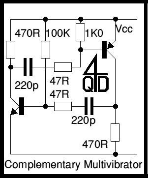
An obvious fact: for all transistor circuits there exists a complement, replace all PNP transistors by NPN and vice versa, reverse all diodes and other 2 terminal polarised components. An identical but complementary circuit results. This is one of the nice things you can do with transistors - but not with ICs. Virtually all ICs have a negative earth and do not work in a complementary version. The reasons for this are mainly historical - the early silicon transistor fabrication made better NPN transistors than PNP. Although modern fabrication makes both, there are very small intrinsic performance differences (due to differences in electron and hole flow) and NPN is therefore the more common model.
But in most two transistor multivib circuits it is possible to replace one of the transistors by its complement (i.e. turn half the circuit 'upside-down' and the circuit still works. The operation is changed, and sometimes some head scratching is required to see the result! Nevertheless it remains a fascinating and instructive exercise!
The diagram above shows the standard multivib with one stage made into its complement. The circuit may look incredibly similar - but the operation is dramatically changed! Instead of the transistors alternating now they both switch on together. The circuit, with an almost trivial change, has stops being a multivibrator and has become a relaxation oscillator!
Which should explain why I do not consider these to be two to be distinct types of circuit! Names are language things: the real world is a continuum and doesn't neatly fit the pigeonholes of language!
Since both transistors conduct simultaneously, the on period is a short pulse followed by a long recovery symptomatic of a relaxation oscillator. To increase the on time, resistors can be put in series with the capacitors as is done in the circuit below.
Yes - this is a slightly different circuit to the above: one of the many circuits I've collected over the years. Source unknown.
Since the collector resistors are connected one each to 0v and to Vcc, why not use a common collector resistor? Indeed - why not also a common base resistor. Both varieties oscillate - so too does the circuit below.
We have derived this, by a few transformations, from a common multivib. Yet this is a series connected multivib! Another language thing, the changes in the real world are trivial! It lead us into a whole new class of multivibrators - where the elements are connected in series rather than in parallel as the first example. And of course, you can do the same PNP - NPN transformations as for the conventional circuit.
The above S.M.V. had was common emitter (the emitters were connected to the supply lines). But for a lot of simple circuits, consider the supply to be a two lead component (a battery). Circuit elements in series can be re-arranged, their order is not important. So let's take our first two complementary multivibs and re-arrange them a bit....
A nice, well behaved oscillator circuit. The diode isn't really needed but it does improve the waveform available on the emitters so that a good sawtooth is available. The values shown give a pulse of about 30µSec every 37mSec. The pulse output may be taken from either collector.
Note also that both halves of this circuit are emitter followers and an emitter follower has a voltage gain of less than 1. Have you been taught that you need voltage gain to make an oscillator? It's not true, current gain alone is enough!
Here's another very simple circuit which oscillates well, even if it gives a lousy waveform!
Warning This page is going to be long: I have a lot of this type of circuit, there is a lot to say. I'm not finished yet but I guess you'd prefer half a page now than a whole page later, so here are a few more circuits (in no particular order) that I'm about to write up... There are many more I have not yet transferred to the computer!
| 4QD Sites: |