
|
4QD-TEC
|
|
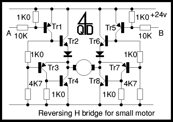
4QD manufacture motor speed controllers so all our H bridges are PWM. Here's a simple switch circuit for reversing and stopping a motor without any control of speed.

Two inputs, A and B, control the bridge. With both high (or open circuit) both ends of the motor are connected to 0v. Connect A low and Tr2 turns on causing the motor to go forward. Connect B low and Tr6 turns on, reversing the motor. If A and B are both low, both ends of the motor are high, so the motor is off.
Tr1 and Tr2 form a complementary darlington. It is normally off (with input A open circuit) and is turned on by connecting input A low.
With Tr1 and 2 off, Tr3 is turned on by the 4K7 base resistor. Tr3 and Tr4 also form a complementary darlington and both turn on together.
Another way of looking at he half bridge is as a totem-pole output stage, with both transistors as complementary darlingtons. The resistor which would normally pull up the base of the top of th pole is replaced by Tr1 which forms also the input to the top-of-the-pole darlington.
Note that no provision is made for recirculating motor currents at switch off. Since the motor is relatively small, the energy at switch off is small and as the circuit is not switching at a high rate, the dumped energy is small, so the breakdown energy in the transistors is not a problem. However - you may like to put reverse parallel flywheel diodes across the transistors.
In the original TO5 transistors were used: 2N3053 for the even numbers and BC214 for the odd numbers. The circuit's nice in that respect - it uses NPN power transistors and PNP drivers in each section of the bridge. You have to chose transistors that will safely switch your motor.
| 4QD Sites: |