
|
|
4QD-TEC
|
|
Audio graphic equalizers are very common as commercial products (for Hi-fi, car audio and stage use) but circuits for them are very rarely published. I didn't design this one but it's really very simple. The details shown are for a 7 band but the principle can be extended to almost any number of bands - if you can find accurate enough components.
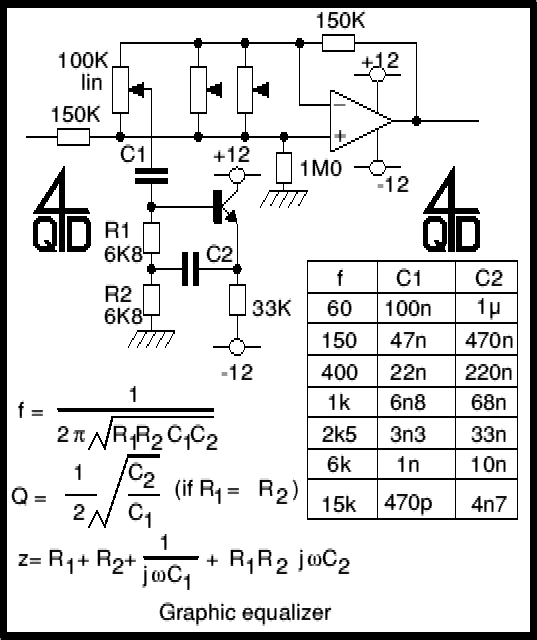
Only one gyrator stage is shown: all 7 gyrators are the same circuit, only the capacitors change, as shown in the chart. I have shown three of the seven faders to show where they go.
A gyrator is a circuit using active devices and transistors to simulate an inductor. In this case the gyrator is the transistor acting with R1, R3 and C2. It could just as easily be a unity gain op-amp (which gives superior performance).
The circuit includes three formulae: one which gives f, the the centre frequency of the band. The second shows how the Q is related to the capacitor ratio. The third shows the impedance presented by the circuit. Note that this includes 3 terms, the first purely resistive, the second is the capacitative contribution from C1 and the third is an inductive term from the gyrator.
If anyone wants the detailed mathematical working out of these formulae, these may be made available to TEC members, in due time. The mathematics for active filters is not as difficult as most tutors tend to make it seem and I really didn't understand it properly until I worked it out for myself and found that it wasn't that complicated, I just hadn't been taught how to understand it! Already available to TEC members is the mathematical analysis of the gyrator circuit used here.
If you do the maths for this you will find the actual frequencies are actually a little different from the target frequencies shown in the diagram: that's what comes from using 'standard' values. Audibly they are plenty close enough.
The rest of the circuit is simply an op-amp. If you consider a 'tuned circuit' (the gyrator) hanging from the pot slider, it is being connected either to the positive input or the negative to a variable extent. One will increase the response at the turned frequency and the other will decrease it.
You must of course chose a good, low noise op-amp: when we manufactured these we used 741s but we selected low noise ones. The transistors also need to be low noise, but you can easily change a noisy transistor if you find you have one.
And that's about it. A very simple, effective circuit. The most difficult bit is going to be sourcing the components - particularly suitable fader pots!.
| 4QD Sites: |