

|
4QD-TEC
|
|
This is a plug-in module which converts 4QD-TEC's transistorised relay into an industrial type timer.
Mention 'timer' to an electronic engineer and most will say '555'. So you may be surprised to hear that there are 8 distinct and different types of timer. The 555 can do some of these - but not all. This division into eight may seem pedantic - but if you want to design a timer, until you have considered all possible alternatives, which ones do you disregard? Consider the diagram:
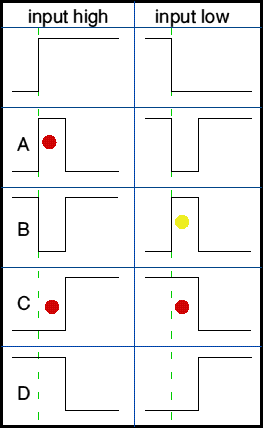
Four of the timers are shown in the left column: these all react to a positive input transition - i.e to the input changing from low to high.
The second column shows the equivalent four timers, but now reacting to a negative going edge.
The three 'important' timers, for industrial control purposes, are shown with a red dot.
The other timers in the diagram may be needed on occasion but with logical and consistent planning I have found that these three alone suffice in most industrial processes. It is interesting that a 555 is really only good at the timer indicated with the yellow dot and actually needs more electronics for most timing functions!
Notice that A and C are similar but one uses the output during the time period and the other uses the output delayed by this same time period. Similarly the two Cs are similar: one is positive logic and the second is a negative logic 'mirror' of the first.
This can be used for the following functions
The drawing shows the implementation of the timer: it's a very simple board yet can be built either as a Delay on Energise (DOE) timer or as a Delay on De-energise (DOD). The DOD timer also has an output which is high during the de-energise delay and it is this which gives the straight 'timer' function.
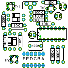
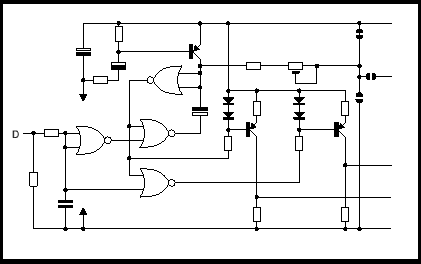
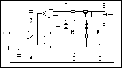
The top circuit is the Delay on energise and straight pulse timer. The second is Delay on de-energise.
The board may be assembled with an on-board preset to adjust the time period. Alternatively the timing point is returned to the 'mother board' where a remote pot can be fitted, as will be required when panel adjustment of the timing period is necessary.
The two circuits are shown below. These are fully described with values. operation and PCB layout in the second part in the private 'members only' area.
| 4QD Sites: |